Thermal protector testing involves verifying whether a temperature-sensitive switch correctly opens and closes a circuit at its rated temperature using continuity tests, controlled heating, and resistance measurement. Proper testing ensures reliable overheating protection in motors, transformers, compressors, and other electrical equipment.
Why Testing Thermal Protectors Is Critical
A thermal protector is the last line of defense against overheating failure in electrical systems. If it fails, consequences may include:
- Motor winding burnout
- Transformer insulation failure
- Compressor overheating damage
- Electrical fire risk
- Unexpected equipment shutdown
Even a small deviation in trip temperature can significantly reduce system safety and lifespan.
👉 Therefore, thermal protector testing is essential in:
- Manufacturing QA
- Maintenance & repair
- Incoming inspection
- Safety certification
What Is a Thermal Protector?
A thermal protector is a temperature-activated safety switch that interrupts or restores electrical circuits when temperature exceeds a preset threshold.
Main Types:
1. Bimetal Thermal Protector (Most Common)
- Snap-action metal disc
- Opens/closes circuit with temperature change
- Resettable (automatic or manual)
2. Thermal Fuse
- One-time cutoff device
- Permanently opens circuit at high temperature
3. Thermistor-Based Protection (PTC / NTC)
- Resistance changes with temperature
- Used in sensing/control systems
Tools Required for Testing Thermal Protectors
To ensure accurate testing, use:
- Digital multimeter (continuity + resistance mode)
- Adjustable heat gun or hot air station
- Temperature probe or infrared thermometer
- Temperature-controlled chamber (for precision testing)
- Safety gloves & insulation tools
Step-by-Step Thermal Protector Testing Procedure
Step 1: Visual Inspection (Always First)
Check for:
- Burn marks or discoloration
- Cracks or mechanical deformation
- Loose terminals or corrosion
- Correct model and temperature rating label
👉 Damaged components should be rejected immediately.
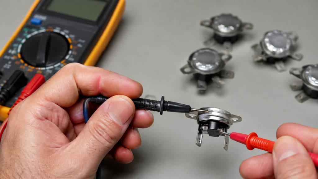
Step 2: Continuity Test (Basic Functional Check)
This is the most widely used field test.
Procedure:
- Set multimeter to continuity / ohm mode
- Connect probes to terminals
- Check initial state
Expected Results:
- Normally Closed (NC): low resistance / beep
- Normally Open (NO): no continuity initially
Step 3: Heating Activation Test (Core Verification)
Procedure:
- Apply controlled heat (heat gun or chamber)
- Gradually increase temperature
- Monitor multimeter reading
Expected Behavior:
- At rated trip temperature → circuit opens
- Resistance becomes infinite (NC type)
- After cooling → resets (if automatic type)
👉 This confirms real thermal response behavior.
Step 4: Thermistor Testing (PTC / NTC Types)
For thermistor-based thermal protection:
NTC Behavior:
- Temperature ↑ → resistance ↓
PTC Behavior:
- Temperature ↑ → resistance ↑
Compare results with datasheet curves.
Step 5: Precision Trip Temperature Test (Engineering Level)
Used in manufacturing or quality labs.
Procedure:
- Place protector in temperature chamber
- Increase temperature gradually (1–2°C/min)
- Record exact switching point
Acceptance Criteria (Industry Typical):
- Trip tolerance: ±5°C to ±10°C
- Reset differential: 10°C–30°C
- Stability: consistent cycling after cooling
Engineering Evaluation Standards (Important for OEM/Manufacturers)
To ensure industrial reliability, evaluate:
Electrical Performance
- Contact resistance: ≤ 50 mΩ
- Dielectric strength: 500V–1500V AC
Thermal Performance
- Trip accuracy: ±5°C (high precision grade)
- Thermal response delay: <10 seconds (typical)
Mechanical Durability
- ≥10,000 switching cycles (motor-grade)
Common Test Results & Failure Diagnosis
| Test Result | Meaning | Possible Cause |
| No continuity at room temp | Failed or tripped | Broken contact or fuse |
| No trip under heat | Faulty protector | Bimetal fatigue |
| Wrong trip temperature | Out of spec | Calibration drift |
| Unstable reset | Mechanical wear | Contact degradation |
Application-Specific Testing Considerations
Motor Thermal Protector Testing
- Must simulate locked rotor current heating
- Embedded winding temperature response critical
Transformer Thermal Protector Testing
- Focus on coil internal temperature response
- Must consider oil or insulation heat transfer delay
Compressor Protection Testing
- Must simulate continuous overload conditions
- High ambient temperature validation required
Common Mistakes in Thermal Protector Testing
❌ Heating too fast (causes false results)
❌ Ignoring installation position effects
❌ Not verifying rated temperature tolerance
❌ Reusing thermal fuses after activation
❌ Testing without load simulation
When Should You Replace a Thermal Protector?
Replace immediately if:
- Trip temperature deviates from specification
- Contact resistance increases abnormally
- Mechanical deformation occurs
- Device is aged (>5–10 years in operation)
- Failure to reset properly
Recommended Thermal Protector Solutions
For industrial-grade applications such as motors and transformers:
SAFTTY Bimetal Thermal Protector Series
- ST01 Series (embedded motor protection)
- ST06 Series (transformer & higher current applications)
- Custom trip temperature: 60°C – 180°C
- Automatic reset / manual reset options
- Designed for coil embedding & varnish resistance
👉 Suitable for:
- Electric motors
- Transformers
- Compressors
- HVAC systems
- Industrial equipment
Why Choose SAFTTY Thermal Protectors?
- Stable snap-action bimetal structure
- High consistency in trip temperature
- Long electrical life cycle
- Strong resistance to epoxy/varnish embedding
- OEM / ODM customization available
Conclusion
Testing thermal protectors is essential for ensuring safe and reliable operation of motors, transformers, and industrial systems. Proper testing includes continuity verification, controlled heating response, and trip temperature validation.
By following standardized testing procedures and engineering criteria, manufacturers and maintenance engineers can significantly reduce equipment failure risk and improve system safety.