One wrong cable ruins a perfect system. RF and microwave engineers know this better than anyone. A signal chain is only as strong as its weakest link, and the coaxial cable assembly is often that link.
Most engineers spend weeks optimising amplifiers, filters, and antennas. Then they reach for any cable off the shelf. That single decision quietly costs them 3 dB of performance.
RF coaxial cable assembly technology is what this guide covers. It explains how these assemblies work, what types exist, and which applications demand what specs.
What Is an RF Coaxial Cable Assembly?
An RF coaxial cable assembly is a cable with RF connectors attached at both ends. It carries high-frequency signals between components in a system. It controls impedance, manages signal loss, and blocks interference. Engineers use it in radar, 5G, satellite systems, and test equipment.
Think of it as the plumbing in your RF system. Water pressure matters, but so do the pipes. If the pipes leak or restrict flow, pressure drops no matter how powerful the pump.
A coaxial assembly has four layers: inner conductor, dielectric, outer shield, and protective jacket. Each layer has a specific job. Together, they keep your signal clean from source to destination.
How Does It Work?
The inner conductor carries the RF signal. The dielectric controls the speed and impedance. The outer shield blocks interference and completes the return path. The jacket protects everything from physical and environmental damage.
Impedance is the critical number here. RF systems run on 50 ohms. Broadcast and video systems use 75 ohms. Put the wrong cable in a 50-ohm system, and you get reflections. Reflections mean lost power and corrupted data.
VSWR (Voltage Standing Wave Ratio) measures how bad those reflections are. A VSWR of 1.0:1 is perfect. Most quality assemblies stay below 1.3:1. Anything above 2.0:1 is a problem you can’t ignore.
Types of RF Coaxial Cable Assemblies
By Cable Type
Not all coaxial cables are the same. The cable type determines how the assembly performs under flex, heat, and frequency pressure.
- Semi-Rigid: Solid outer conductor. Best phase stability. Fixed installation only. Can’t re-bend once shaped.
- Semi-Flexible: Similar performance to semi-rigid. Allows re-bending. Good for tight spaces with limited movement.
- Flexible: Braided shield. Best for test benches and anywhere the cable moves regularly.
- Conformable: Bends like flexible, holds shape like semi-rigid. Good middle ground for complex routing.
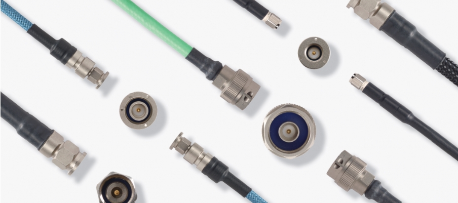
By Connector Type
The connector is the handshake between your cable and your system. Get it wrong, and nothing works. Here are the most common types by frequency range:
- SMA: Up to 18 GHz. The most common connector in microwave engineering.
- N-Type: Up to 18 GHz. Robust, weatherproof, high-power capable.
- BNC: Up to 4 GHz. Standard in lab instruments and signal generators.
- 2.92mm (K-connector): Up to 40 GHz. Preferred for millimeter-wave test setups.
- 2.4mm: Up to 50 GHz. High-frequency lab and measurement standard.
- 1.85mm (V-connector): Up to 67 GHz. Used in advanced mmWave systems.
Specs That Actually Matter
Insertion Loss
Insertion loss is the tax your signal pays to travel through the cable. It’s measured in dB per metre. A standard flexible SMA cable loses around 0.5 dB/m at 1 GHz. At 40 GHz, that same cable loses over 5 dB/m.
Low-loss cables use foam PTFE dielectric instead of solid PTFE. This alone cuts loss by 30-40%. For long cable runs or high-frequency systems, that difference is significant.
Phase Stability
Phase stability is how well the cable holds its electrical length when flexed or exposed to temperature changes. In a phased array antenna, every element needs to be phase-matched. A 5-degree phase error across 64 elements destroys beam accuracy.
Phase-stable cables use special materials that resist electrical length changes under mechanical stress. They cost more. But in radar, satellite, or 5G front-haul systems, they’re not optional.
Power Handling
Power handling depends on cable diameter, connector type, and frequency. Larger diameter means lower resistance and better heat management. N-type connectors handle more power than SMA. At higher frequencies, power ratings drop significantly.
Where RF Engineers Actually Use These
Radar and Antenna Systems
In radar, the feed line between the transmitter and antenna is mission-critical. Every 0.1 dB of loss reduces effective radiated power. In a high-power radar, that translates directly to reduced detection range.
Phase-matched cable sets are standard in phased array systems. All cables in the array must have the same electrical length. Even a 1 mm difference causes measurable beam-pointing errors.
Defense and Electronic Warfare
EW systems need broadband coverage, often from 2 GHz to 40 GHz in a single assembly. Cable assemblies in these platforms face jet fuel, salt fog, extreme vibration, and temperature swings from -55°C to +125°C.
Cables in this environment must meet MIL-DTL-17 standards. That’s not a preference. It’s a contract requirement. Standard commercial cables fail these tests. Military-grade assemblies don’t.
Test and Measurement
A VNA is only as accurate as the cable connecting it to the device under test. A cable with VSWR above 1.2:1 introduces measurement uncertainty that masks what you’re actually trying to measure.
Test cables take thousands of flex cycles in a busy lab. Phase stability under flex matters as much as initial loss performance. Cheap cables drift. Good cables don’t.
5G and Telecom Infrastructure
5G mmWave deployments run at 24 GHz to 71 GHz. At those frequencies, every connector junction and cable metre matters. Front-haul links between radio units and antennas run outdoors, in all weather, 24/7.
Phase matching across all antenna ports keeps the beam stable. Temperature cycles from day to night shift cable electrical length. Assemblies built for 5G infrastructure use materials that minimise this drift.
Satellite Communications
Satellite ground stations use cable assemblies across Ku, Ka, and Q/V bands. These frequencies run from 12 GHz to 75 GHz. Every dB of loss in the feed chain reduces link margin.
Space-grade assemblies face a harder challenge. Thermal cycling from -180°C to +150°C causes standard materials to crack or deform. Space-rated cables use PTFE-based dielectrics and special plating to survive these conditions.
Medical Imaging
MRI systems generate strong RF pulses at specific frequencies. A 1.5T MRI operates at 64 MHz. A 3T MRI operates at 128 MHz. The cable assemblies delivering these pulses to the body coil must be non-magnetic.
Magnetic materials distort the imaging field. Even small amounts of ferromagnetic content in a connector cause visible artefacts in the scan. Medical-grade RF assemblies use non-magnetic materials throughout.
How to Pick the Right Assembly
Selection is a process, not a guess. Work through these steps before buying:
- Set your frequency ceiling: Pick an assembly rated 20-30% above your actual operating frequency.
- Calculate your loss budget: Add up all cable losses in the signal chain. The total must sit within your system’s design margin.
- Match your connector: Confirm connector type, thread, gender, and impedance before ordering.
- Check the flex requirement: Fixed installation? Use semi-rigid. Moving cable? Use flexible or conformable.
- Review environmental specs: Temperature range, IP rating, and chemical resistance must match your deployment.
- Assess phase requirements: Array or measurement systems need phase-stable or phase-matched sets.
- Custom vs. standard: Non-standard lengths or connector combinations often need custom assemblies.
Mistakes That Cost Engineers Time and Money
Most coaxial cable failures come from the same handful of mistakes. Here’s what to avoid:
- Impedance mismatch: A 75-ohm cable in a 50-ohm system creates VSWR above 1.5:1. Avoid it.
- Over-bending semi-rigid: Exceed the minimum bend radius and the outer conductor cracks. Phase stability is gone.
- Skipping torque specs: SMA connectors need 5-8 inch-pounds of torque. Under-torque causes intermittent contact. Over-torque strips threads.
- Wrong cable length: In phase-sensitive systems, a 5 mm length error causes measurable phase imbalance.
- Ignoring cable wear: Flexible test cables have a finite flex cycle life. Replace them on schedule.
Why Engineers Choose ZOMWAVE
ZOMWAVE builds RF coaxial cable assemblies for engineers who can’t afford to compromise. Every assembly goes through insertion loss testing, VSWR characterisation, and phase verification before it ships.
The product range covers flexible, semi-rigid, conformable, and phase-stable assemblies. Connector options include SMA, N-type, 2.92mm, 2.4mm, and 1.85mm. Standard and custom lengths are available for OEM and system integrator applications.
If your application sits outside standard parameters, the engineering team works with you on custom configurations. The spec sheet is the starting point, not the limit.
Final Word
The cable is never just a cable. In an RF system, it’s an active part of the performance equation. Pick it wrong, and the whole chain suffers.
Know your frequency. Know your loss budget. Know your environment. Match those three factors to the right assembly, and your system performs as designed.
The engineering is in the details. That’s where good RF work lives.