Introduction
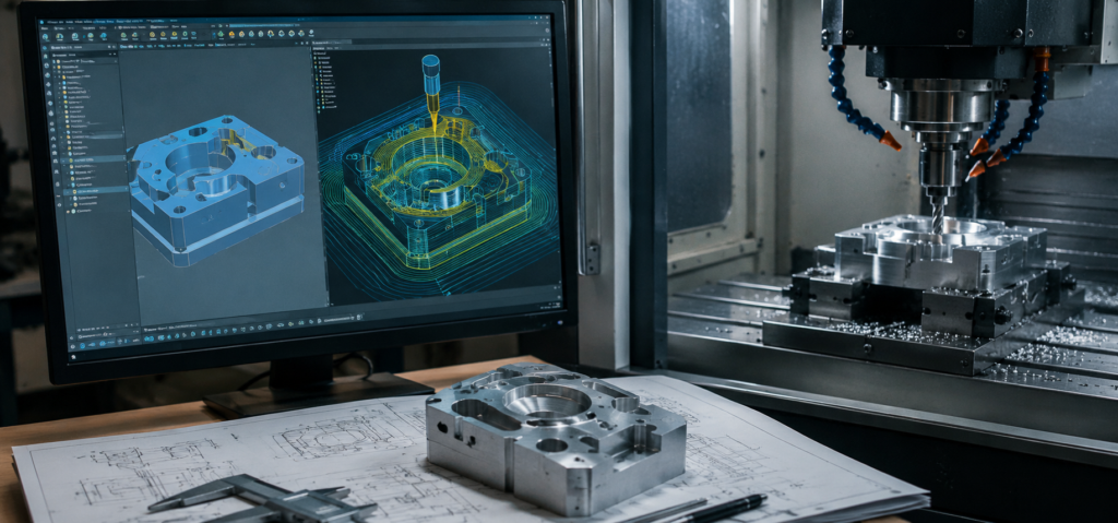
A finished CAD model on screen and a finished part on a machinist’s table are separated by more steps than most people outside manufacturing realize. Between the two sits an entire discipline, computer-aided manufacturing, that takes precise 3D geometry and translates it into the exact, numeric instructions a CNC machine needs to actually cut metal or plastic. Understanding that translation process, from solid model to toolpath to G-code, helps engineers design parts that machine efficiently instead of fighting the manufacturing process after the fact.
The CAD-to-CNC Pipeline, Step by Step
Getting from a 3D model to a finished machined part generally follows four stages:
- CAD design — the part is modeled as a precise, dimensioned solid model
- CAM programming — computer-aided manufacturing software reads that geometry and generates toolpaths describing how a cutting tool will remove material
- Post-processing — those toolpaths are converted into G-code, the specific numeric language a given CNC machine’s controller understands
- Machine execution — the CNC machine reads the G-code and moves its cutting tool accordingly, removing material until the finished part matches the original model
Each stage depends heavily on the quality of what came before it, which is why a clean, accurate CAD model has effects that ripple all the way through to the final part on the machine.
What Happens Inside CAM Software
CAM software is where a 3D model actually becomes a manufacturing plan. After importing the CAD geometry, a machinist or manufacturing engineer defines the setup: the raw stock material’s size and shape, how the part is oriented and fixtured, and which specific features need to be machined.
From there, the software defines individual machining operations tied to specific features of the part:
- Roughing — removing bulk material quickly to get close to the final shape, prioritizing speed over finish quality
- Finishing — a slower, more precise pass that brings the part to its final dimensions and surface finish
- Pocketing — clearing material from an enclosed cavity or recess
- Contouring — following the outer or inner profile of a feature
- Drilling — creating holes using standard drill cycles rather than general-purpose milling
For each operation, the programmer selects an appropriate cutting tool, an end mill, drill, or specialty cutter, and sets cutting parameters including spindle speed, feed rate, depth of cut, and stepover (how much the tool overlaps its previous pass). These parameters directly affect cycle time, tool wear, and surface finish, and they’re chosen based on the material being cut and the tool’s own specifications.
Common Toolpath Strategies
CAM software offers several distinct toolpath strategies, each suited to different geometry and material removal goals:
Adaptive Clearing (High-Speed Machining)
Rather than taking a single deep, wide cut, adaptive clearing maintains a constant, controlled engagement between the tool and the material by adjusting the path dynamically. This reduces tool stress and heat buildup, often allowing faster overall material removal despite each individual pass being lighter.
Contour Milling
The tool follows the outer or inner boundary of a feature, commonly used for finishing the walls of a part or cutting an outer profile to its final shape.
Pocket Milling
Used to clear material from an enclosed cavity, pocket milling strategies typically work inward or outward in a systematic pattern to fully clear the pocket floor while respecting the pocket’s wall boundaries.
Parallel Finishing
The tool moves in a series of straight, parallel passes across a surface, commonly used for finishing broad, relatively flat or gently curved surfaces where a consistent, uniform finish matters.
CAM software calculates each of these strategies directly from the part’s geometry, meaning the accuracy and cleanliness of the underlying CAD model has a direct effect on how correctly these toolpaths are generated.
Post-Processing and G-Code
Once toolpaths are calculated, they still aren’t in a form any specific CNC machine can execute directly. A post-processor converts the generic toolpath data into G-code, the standardized but machine-specific set of numeric commands that controls tool position, movement speed, spindle activation, and other machine functions.
Post-processors are specific to a given combination of CNC machine and controller, because different machine builders and controller manufacturers implement slightly different command sets, axis conventions, and machine-specific behaviors. A toolpath generated in CAM software has to be post-processed correctly for the exact machine it will run on; using the wrong post-processor can produce G-code that runs incorrectly or, in a worst case, damages the machine or the part.
Why Clean CAD Geometry Matters
CAM software depends entirely on the geometry it’s given, and problems in a CAD model tend to surface as problems in the toolpath, or worse, in the finished part.
Non-manifold geometry (edges or surfaces that don’t properly close into a valid solid) can confuse CAM software’s ability to correctly identify surfaces to machine. Small gaps or overlapping surfaces, often invisible on screen, can cause a toolpath to skip a region entirely or generate an unnecessary, time-wasting pass. Overly complex or unnecessarily fine features can force CAM software to calculate toolpaths far more slowly, or require smaller, more fragile tooling than the part’s actual function demands.
Accurate dimensions and tolerances established in the CAD model also carry directly through to the finished part. A tolerance that’s tighter than the application actually requires increases machining time and cost without a corresponding functional benefit, which is why thoughtful CAD design, not just CAM programming, plays a direct role in manufacturing efficiency.
Simulation and Verification Before Cutting
Before any toolpath actually runs on a physical machine, CAM software simulates the entire machining sequence virtually, checking for tool collisions with fixtures or clamps, gouges where the tool removes more material than intended, and other errors that would otherwise only be discovered at the machine, often at the cost of scrapped material or a damaged tool. This simulation step is one of the most valuable parts of the CAD-to-CNC pipeline, since catching a programming error on screen is dramatically cheaper than catching it mid-cut.
Designing With Manufacturing in Mind
Because CAD geometry drives every downstream step, designing with machining realities in mind, sometimes called design for manufacturing, meaningfully improves how efficiently a part moves through this pipeline. Practical habits include using standard hole sizes that match common drill diameters, adding fillets that match realistic cutter radii instead of sharp internal corners, and keeping features accessible to standard-length tools rather than requiring long, flexible tooling prone to vibration.
This is where the CAD environment itself matters. Browser-based CAD platforms like HVH Designer support this kind of manufacturing-aware design directly in the modeling process, and because HVH Designer includes an integrated 3D Parts Library of certified, manufacturer-accurate standard components, features like fasteners, bearings, and couplings arrive with correct, real-world geometry already built in, rather than being approximated by hand and potentially introducing exactly the kind of small geometric inconsistencies that cause problems downstream in CAM software.
Conclusion
The path from a CAD model to a finished CNC-machined part runs through CAM software, careful toolpath strategy selection, machine-specific post-processing, and simulation, each stage translating the previous one’s output into something more specific and more machine-ready. Clean, accurate CAD geometry isn’t a separate concern from manufacturing, it’s the foundation the entire toolpath generation process depends on, which is exactly why designing with machining realities in mind from the very first sketch pays off long before a part ever reaches the machine.