
How EV High Voltage Safety Systems Detect Faults and Safely Disconnect Power

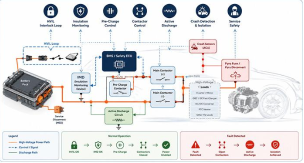
See how insulation monitoring, high-voltage interlocks, contactors, pre-charge circuits and emergency isolation work together to protect the vehicle, its occupants and the people who service it.
Modern electric vehicles operate with battery voltages high enough to create serious shock, electrical-arc and fire hazards when the system is damaged, opened or serviced incorrectly. The traction battery, inverter, electric drive, onboard charger and DC-link components must therefore remain electrically isolated, mechanically protected and continuously supervised throughout the vehicle lifecycle.
Protecting this network requires a coordinated High-Voltage Energy & Safety architecture that combines insulation monitoring, interlock detection, contactor control, pre-charge, active discharge, crash isolation and clearly defined service procedures.
What must the vehicle verify before high voltage is enabled?
Each safety function answers a different question, but the vehicle must evaluate all of them as one coordinated system.
- Are the high-voltage connectors fully locked?
- Is the battery enclosure correctly closed?
- Is insulation to the vehicle chassis healthy?
- Can the main contactors close safely?
- Has the high-voltage path opened after a fault?
- Has residual DC-link energy been discharged?
The effectiveness of the protection system depends not only on the individual components you select, but also on how sensing, decision-making and physical disconnection are coordinated across the vehicle.
Why EV High-Voltage Safety Requires Multiple Protection Layers
When you evaluate an electric vehicle’s high-voltage system, no single sensor, fuse or shutdown device can protect against every possible failure. A damaged cable, an unlocked connector, a severe collision and an incorrect service procedure create very different risks, and each one develops in a different way.
A reliable design therefore uses several independent protection layers. Some layers detect changes in electrical insulation, while others verify physical connector integrity, control the high-voltage current path or provide emergency isolation when normal electronic control may no longer be enough.
Electrical Insulation Faults
Insulation faults can allow high-voltage energy to leak toward the vehicle chassis or other unintended conductive paths. These faults may develop gradually, making continuous monitoring especially important.
- Damaged insulation around high-voltage cables
- Coolant leakage, condensation or moisture ingress
- Contamination across connector pins or PCB surfaces
- Degradation in motor windings, heaters or power electronics
Mechanical Access Faults
The electrical system may remain healthy while a physical safety boundary is no longer secure. That is why the vehicle must also verify connector engagement, enclosure access and service-disconnect position.
- A high-voltage connector that is not fully latched
- An opened battery enclosure or service cover
- A removed or incorrectly installed manual service disconnect
- Connector movement caused by vibration or incomplete engagement
Crash-Related Faults
During a collision, mechanical deformation and electrical faults may occur at the same time. Normal contactor control may need to be supported by additional physical isolation measures.
- Battery-pack compression or structural intrusion
- Deformation of internal busbars or high-current connections
- Cut, crushed or exposed high-voltage wiring
- Main contactors that become welded under severe fault current
Service-Related Hazards
A vehicle that appears to be switched off may still contain hazardous stored energy. Safe service depends on a defined depowering procedure rather than assumptions about the system state.
- Assuming that opening the contactors makes every circuit safe
- Residual energy remaining in DC-link capacitors
- Disconnecting high-voltage components in the wrong sequence
- Skipping lockout, discharge waiting time or voltage verification
Because these hazards have different causes and develop at different speeds, EV platforms use several independent but coordinated protection mechanisms rather than relying on a single shutdown device. The purpose of this layered approach is not simply to detect a fault, but to move the vehicle toward a predictable and verifiable safe state.
Electrical Isolation and the Floating High-Voltage Architecture
In a conventional 12 V vehicle electrical system, the metal chassis is commonly used as part of the normal current-return path. An EV traction system is designed differently. Its high-voltage positive and negative conductors are normally kept electrically isolated from the vehicle body.
This arrangement is often described as a floating high-voltage system. Current is intended to flow between the positive and negative sides of the traction circuit rather than through the chassis. As a result, one insulation defect may not immediately create a complete current path through the body of the vehicle.
The chassis may form part of the normal circuit
In many 12 V systems, the negative battery terminal is connected to the metal body. Components can use the chassis as a shared electrical return path, reducing the amount of dedicated return wiring required.
The chassis should remain outside the normal current path
In an isolated traction system, both high-voltage conductors remain separated from the vehicle body. The chassis is treated as a reference for detecting insulation degradation, not as the intended return conductor for traction current.
What electrical isolation changes in practice
- A single insulation defect may not immediately complete a hazardous current path.
- The chassis can be monitored as a reference for detecting leakage and insulation loss.
- A second insulation fault could create a more serious current path if the first fault is not detected.
- Continuous supervision is still required during startup, charging, driving and service.
A floating architecture reduces the likelihood that a single insulation fault will create a complete current path, but it does not make electric shock impossible. It also does not remove the need for continuous insulation monitoring, fault diagnosis and safe shutdown logic.
Electrical isolation provides the foundation of the high-voltage safety architecture, but the vehicle still needs an active way to detect when that isolation begins to deteriorate. The next protection layer therefore monitors the resistance between the high-voltage network and the chassis so that moisture, cable damage and insulation ageing can be identified before they develop into a more serious hazard.
Insulation Monitoring for Leakage, Moisture and Degradation
Electrical isolation only protects the vehicle while the insulation around cables, connectors, motors and power-electronic components remains healthy. Because insulation can deteriorate gradually, you need a monitoring function that can detect changes before they develop into a more serious shock, leakage or shutdown risk.
An insulation monitoring device, commonly referred to as an IMD, continuously evaluates the relationship between the high-voltage network and the vehicle chassis. Instead of waiting for a direct short circuit, it helps you identify weakening insulation, moisture-related leakage and other abnormal current paths at an earlier stage.
What the insulation monitor continuously checks
The IMD looks at the entire high-voltage network rather than monitoring only one cable or one connector.
Positive Side: Insulation between the high-voltage positive conductor and the vehicle chassis.
Negative Side: Insulation between the high-voltage negative conductor and the vehicle chassis.
Network Condition: The effective insulation resistance of the complete traction and charging network.
Degradation: Changes caused by moisture, coolant leakage, contamination, ageing or damaged insulation.
Faults may develop before a direct short occurs
In real operating environments, insulation rarely changes from healthy to completely failed in one step. You may first see a gradual reduction in resistance caused by:
- Moisture or condensation inside connectors and enclosures
- Coolant leakage near the battery, inverter or electric drive
- Cable abrasion caused by vibration or incorrect routing
- Ageing in motor windings, heaters or high-voltage electronics
The response depends on fault severity and vehicle state
When the IMD detects an abnormal condition, the safety ECU or BMS does not always respond in exactly the same way. Depending on the measured resistance, persistence and operating state, the vehicle may:
- Record a diagnostic fault and store operating data
- Display a warning to the driver or service technician
- Block the next high-voltage startup
- Limit vehicle power or request a controlled stop
- Open the main contactors when isolation is required
IMD and HVIL answer different safety questions
Insulation Monitoring: The IMD tells you whether the high-voltage network remains electrically isolated from the chassis.
High-Voltage Interlock: The HVIL tells you whether monitored connectors, covers and service disconnects remain physically secured.
A healthy IMD result does not prove that a connector is fully locked. A healthy HVIL result does not prove that cable insulation, coolant barriers or motor windings remain electrically sound. You need both layers because they protect against different failure modes.
Insulation monitoring identifies electrical leakage and insulation degradation, while another protection layer is required to determine whether high-voltage connectors, covers and service disconnects remain physically secured.
HVIL Detection for Connectors, Covers and Service Disconnects
The high-voltage interlock loop is a low-voltage circuit routed through critical high-voltage connectors, service disconnects and battery-enclosure access points. When every monitored component is correctly installed, the loop remains electrically complete.
If a connector is removed, a cover is opened or a service plug is disengaged, the loop condition changes. The vehicle can then identify that a physical safety boundary may no longer be secure before allowing high-voltage energy to remain connected.
Where the HVIL loop may be routed
1: Battery-pack covers
2: Service disconnects
3: High-voltage connectors
4: Charge-inlet interfaces
5: Inverter and e-axle links
A direct MCU input may look sufficient
On a short prototype loop, you may be able to use a pull-up resistor and a GPIO to identify whether the circuit is open or closed. That approach is easy to understand, but it provides little information about why the loop changed state.
A vehicle loop must classify real-world faults
A production monitor may need to distinguish a true open circuit from a short to ground, short to battery, intermittent connector movement or a high-resistance leakage path. It must also reject temporary disturbances without hiding a genuine safety event.
Why HVIL monitoring becomes more difficult in a real vehicle
- A long HVIL harness can pick up noise from nearby switching systems.
- Connector contacts may chatter briefly during vibration or incomplete engagement.
- Inverter and charger switching can introduce EMI and high-dv/dt disturbances.
- Moisture or contamination can create a high-resistance leakage path instead of a clean open.
- Open-circuit and short-circuit conditions may require separate voltage windows.
- Temporary disturbances must be filtered without delaying a persistent fault response.
A reliable interlock circuit must distinguish a genuine connector or enclosure fault from temporary chatter, EMI and harness-related disturbances. The HVIL Monitor for High-Voltage Interlock Safety guide explains how loop architecture, input protection, voltage windows, debounce, diagnostics and IC selection can be translated into practical design requirements.
The vehicle response depends on when the HVIL fault occurs
Before Startup: The fault may block pre-charge and prevent the main contactors from closing.
During Pre-Charge: The state machine may stop the sequence and return the high-voltage system to a safe state.
While Driving: The controller may request torque reduction, a controlled stop or contactor opening.
After Shutdown: The system may store the fault, block restart and verify that residual voltage is safely reduced.
An HVIL fault is therefore not a single universal shutdown command. Its meaning and response depend on the vehicle state, fault persistence and safety strategy, but the objective remains the same: prevent high-voltage energy from remaining connected when the physical containment path can no longer be trusted.
How the BMS, BDU and Contactors Control the High-Voltage Path
Detecting an unsafe condition is only the first part of high-voltage protection. Once the vehicle identifies an insulation fault, an open interlock loop, an abnormal voltage or a communication failure, it must decide whether the traction battery can remain connected to the rest of the vehicle.
That decision is normally shared across the BMS or safety ECU, the Battery Disconnect Unit and the main contactors. Each part has a different responsibility: one evaluates the system state, one contains the high-voltage switching hardware and one physically opens or closes the power path.
BMS or Safety ECU
This controller brings together the information needed to decide whether the high-voltage system can be energized, remain active or move into a safe shutdown state.
- Reads HVIL and IMD status
- Checks cell voltage, pack voltage and temperature
- Verifies communication and sensor plausibility
- Executes the high-voltage state machine
- Grants or blocks permission to energize the bus
Battery Disconnect Unit
The BDU is the controlled gateway between the battery pack and the external high-voltage network. Its exact contents vary by platform, but it commonly combines switching, sensing and fault-isolation functions.
- Main positive contactor
- Main negative contactor
- Pre-charge contactor
- Current sensing
- Main fuse
- Pyrotechnic disconnect
- HVIL monitoring
Main Contactors
The contactors form the main electromechanical connection between the battery and the vehicle’s high-voltage loads. When open, they are intended to isolate the external bus from the traction battery.
- Inverter and electric drive
- Onboard charger and fast-charge path
- High-voltage DC/DC converter
- Electric air-conditioning compressor
- PTC heater and auxiliary HV loads
From fault information to physical disconnection
1 Sense HVIL, IMD, voltage, current and temperature inputs → 2 Evaluate BMS or safety ECU checks plausibility and operating state → 3 Command Contactor drivers receive a close or open request → 4 Verify Feedback confirms whether the electrical path changed as expected
A software command is not proof of electrical isolation
When the controller sends an “open” command, you still need evidence that the high-voltage path has actually opened. A contactor may respond slowly, an auxiliary contact may disagree with the commanded state or the main contacts may remain welded after a severe current event.
- Check the contactor auxiliary contacts
- Measure battery-side and load-side voltage
- Verify that the bus voltage follows the expected state
- Detect a welded or mechanically stuck contactor
- Confirm that the discharge path is reducing voltage
Before the main contactors can close, the downstream DC-link capacitance must also be charged in a controlled manner. Without that step, the initial current surge could damage the very switching components intended to protect the system.
Pre-Charge Prevents Inrush Current During High-Voltage Startup
The inverter, onboard charger and other high-voltage power-electronic systems contain large DC-link capacitors. When the vehicle is off, these capacitors may be at a much lower voltage than the traction battery. Connecting them directly to the battery would create a very large and sudden charging current.
The pre-charge circuit gives you a controlled way to raise the downstream bus voltage before the main power path is fully connected. This reduces stress on contactor contacts, fuses, busbars, connectors and the input stages of the vehicle’s power electronics.
What could happen without controlled pre-charge?
01: Full battery voltage is applied to an uncharged capacitor bank.
02: A high inrush current flows through the contactor and busbars.
03: Contactor surfaces may arc, erode or weld together.
04: A protective fuse may operate even when no downstream fault exists.
05: Connectors and power-electronic inputs experience unnecessary stress.
Pre-Charge Resistor
Limits the initial charging current so the downstream capacitors gain voltage gradually instead of drawing an uncontrolled surge.
Pre-Charge Contactor
Temporarily connects the resistor path while the controller observes whether the bus voltage rises as expected.
Voltage Feedback
Allows the BMS or safety ECU to compare battery voltage with the downstream bus and decide when the main power path can be completed.
A typical pre-charge sequence
1: Confirm that the HVIL status is valid and no physical interlock fault is present.
2: Confirm that insulation conditions, voltage signals and other startup checks are within the permitted range.
3: Close one main contactor according to the platform’s selected switching architecture.
4: Connect the pre-charge resistor path and begin charging the downstream DC-link capacitors.
5: Monitor the bus-voltage rise and check that it follows the expected timing and shape.
6: Close the remaining main contactor when the downstream voltage reaches the platform’s permitted threshold.
7: Open the pre-charge branch so normal operating current flows through the main contactors.
The switching order is platform-dependent
You should not assume that every EV closes the positive contactor first or follows one universal contactor sequence. The order depends on the BDU architecture, sensing arrangement, fault strategy and vehicle manufacturer. What matters is that the controller limits inrush current, verifies the voltage response and confirms that the final contactor state matches the requested state.
The voltage curve also reveals hidden faults
- Voltage rises too slowly: The resistor path, contactor or wiring may have excessive resistance or an open connection.
- Voltage rises too quickly: A main contactor may already be closed or welded, bypassing the controlled resistor path.
- Voltage stops below target: A downstream load, short or abnormal capacitance may prevent the bus from reaching the required level.
- Voltage signals disagree: A sensor, wiring path or measurement reference may be producing an implausible result.
Pre-charge controls how energy enters the high-voltage bus. After the system is shut down, the opposite challenge remains: the vehicle must also control how residual energy leaves the bus and verify that stored voltage has fallen to a safe level.
Active Discharge Reduces Residual Voltage After Shutdown
Opening the main contactors disconnects the traction battery from much of the external high-voltage network, but it does not automatically make every downstream component safe to touch. The inverter, onboard charger and other power-electronic systems can still hold energy inside their DC-link capacitors.
Without a controlled discharge path, the high-voltage bus may remain energized after the vehicle has been switched off. You therefore cannot determine whether the system is safe only by checking the commanded contactor state. The remaining voltage must also be measured and reduced within the shutdown time required by the vehicle architecture.
Why hazardous voltage may remain after the contactors open
Capacitors Store Energy
Large capacitors inside the inverter and charger can remain charged even after the battery path has been opened.
Bus Voltage Falls Gradually
The downstream bus does not necessarily fall to a safe level immediately unless a defined discharge path is available.
Contactors Are Not Enough
An open contactor command does not prove that all stored energy has been removed from the high-voltage loads.
Voltage Must Be Verified
The control system and service procedure should confirm that residual voltage has fallen as expected.
How an active discharge path may be implemented
Discharge Resistor
Converts stored electrical energy into heat while limiting discharge current to a level that the circuit can safely handle.
Power MOSFET or IGBT
Connects the discharge path when shutdown is requested and isolates it during normal vehicle operation.
Internal Discharge Path
Some inverters, chargers and power modules include a built-in path that can discharge their local DC-link capacitance.
Voltage Monitoring
Tracks the high-voltage bus during shutdown so the controller can verify that voltage is falling within the expected time.
Controller Oversight
Coordinates the contactor state, activates the discharge path and compares measured voltage with the expected shutdown profile.
What a controlled shutdown should confirm
- 1 Isolation Requested The controller commands the main high-voltage path to open.
- 2 Contactors Verified Feedback and voltage measurements confirm the expected switching state.
- 3 Discharge Activated Stored energy is routed through the controlled discharge network.
- 4 Voltage Tracked The controller checks the DC-link voltage decay over time.
- 5 Safe State Confirmed Service access remains blocked until the required voltage condition is verified.
The discharge network reduces residual DC-link voltage to the required safe level within the shutdown time defined by the vehicle architecture and applicable safety requirements. The exact voltage threshold and permitted discharge time depend on the platform, components and compliance targets.
The system must also detect when discharge does not work
- Open Discharge Path: A failed resistor, switch or connection may prevent current from flowing through the intended path.
- Unexpected Voltage Decay: Voltage that falls too slowly or remains stable may indicate that the discharge function has not activated.
- Abnormal Capacitance: A damaged component or unexpected load condition may change the normal discharge profile.
- Implausible Sensor Reading: The controller should identify a voltage signal that conflicts with contactor feedback or other measurements.
Active discharge completes the normal shutdown process by removing stored energy from the high-voltage bus. During a severe collision, however, damaged wiring, welded contacts or lost control power may require a more direct and irreversible isolation method.
Crash Detection and Emergency High-Voltage Isolation
A serious collision can create electrical and mechanical failures at the same time. High-voltage cables may be crushed, the battery enclosure may be deformed and contactors may be exposed to fault currents high enough to damage their switching surfaces.
Under these conditions, the vehicle cannot rely only on normal shutdown commands. The high-voltage safety strategy must combine crash detection, torque interruption, contactor control, active discharge and, where required, an additional physical disconnection mechanism.
Signals that may initiate an emergency isolation response
- ACU Airbag Control Unit Provides validated collision information to the vehicle safety network.
- Crash Sensors: Detect impact events at selected positions around the vehicle.
- G Acceleration Sensors Measure rapid deceleration and impact-related motion.
- ↻ Rollover Detection Identifies vehicle motion that may expose the battery and cables to additional damage.
- BI Battery Intrusion Sensors Detect deformation or intrusion near the battery enclosure.
- CAN Safety Network Distributes confirmed crash status to the BMS, inverter and other controllers.
How the vehicle may respond to a severe crash
- Stop Torque Production: The inverter is instructed to stop driving the motor and enter a controlled safe state.
- Open Main Contactors: The battery path is commanded open when the contactors remain capable of switching.
- Activate Discharge: Residual voltage in the downstream bus is reduced when the discharge system remains available.
- Disable Charging: Charging interfaces and onboard charging functions are prevented from energizing the damaged system.
- Broadcast HV Fault: The vehicle network reports that the high-voltage system is in a crash-related isolation state.
- Trigger Emergency Isolation: A pyrotechnic device may sever the high-current path when irreversible isolation is required.
Why normal contactors may not provide enough isolation
Contactors are designed for repeated controlled switching, but a severe crash can create conditions outside normal operation.
- Extremely high short-circuit current
- Welded main contacts
- Mechanical deformation of the BDU
- Loss of low-voltage control power
What a pyrotechnic disconnect adds
A pyrotechnic fuse or disconnect uses an electrically initiated mechanism to physically interrupt the high-current conductor. Once activated, the path cannot be restored without replacing the device.
This provides an additional isolation layer when the vehicle cannot rely on normal contactor movement or when the safety concept requires a guaranteed physical break in the main power path.
In platforms that require an additional irreversible isolation layer, a pyrotechnic disconnect can physically sever the high-current path during severe crash or fault conditions. Not every EV uses the same device, activation threshold or switching sequence, so the function must be integrated into the specific vehicle safety concept.
Normal shutdown and crash isolation serve different conditions
Controlled and potentially reversible
The BMS opens the contactors, activates discharge, records the fault and may allow the system to operate again after diagnosis and repair.
Immediate and potentially irreversible
The vehicle may use contactors together with a pyrotechnic device to create a physical break that requires component replacement before high voltage can be restored.
Emergency isolation is most effective when crash sensors, the safety ECU, contactor drivers, discharge circuits and pyrotechnic devices are treated as one coordinated response chain. The objective is not simply to issue a shutdown command, but to create and verify a predictable high-voltage safe state even when parts of the vehicle may already be damaged.
Mechanical Protection of the Battery Pack and High-Voltage Components
Electrical monitoring and emergency isolation can reduce the consequences of a fault, but your first line of defence is often preventing physical damage from reaching the battery cells, busbars, connectors and high-voltage cables in the first place.
A well-designed battery-pack enclosure must manage road impact, side intrusion, vibration, water exposure and internal pressure without allowing sensitive high-voltage components to move into unsafe positions. Structural protection does not replace fault detection, but it reduces the probability that a mechanical event will become an electrical hazard.
The main structural protections you may find around an EV battery pack
Rigid Pack Enclosure
A reinforced metal or composite enclosure helps keep modules, sensing circuits and high-voltage conductors within a controlled structure.
Underbody Impact Protection
Skid plates, reinforced trays and controlled deformation zones help protect the pack from road debris and bottom impact.
Side-Impact Load Paths
Cross-members, rails and surrounding body structures redirect crash loads away from the most vulnerable battery areas.
Module Separation
Physical spacing, barriers and controlled mounting reduce the likelihood that movement in one area will damage adjacent modules.
Busbar Intrusion Protection
Internal shields and protected routing help prevent conductive structures from contacting or deforming the high-voltage busbars.
Water Sealing and Drainage
Gaskets, sealed connectors, drainage paths and pressure-management features reduce moisture accumulation inside the pack.
Pressure Relief and Venting
Defined venting routes help direct pressure and gases away from sensitive components and vehicle occupants.
Harness Retention
Clamps, strain relief and abrasion-resistant routing prevent high-voltage cables from rubbing, stretching or contacting sharp edges.
Prevent contact and uncontrolled movement
The structure should prevent cells, modules, busbars and connectors from shifting into each other during vibration or impact. Mounting points and internal clearances must remain predictable as the pack experiences real vehicle loads.
Preserve the electrical safety functions
Crash protection should also protect sensing lines, contactor controls, the HVIL circuit and voltage-measurement paths so the vehicle can still detect damage and initiate high-voltage isolation.
Mechanical protection lowers the likelihood of a damaged battery or exposed conductor, but it cannot prove that the high-voltage network is electrically safe. After an impact, water-ingress event or enclosure deformation, the system must still rely on fault detection, contactor isolation, discharge monitoring and direct voltage verification.
Structural protection reduces the probability of damage, but maintenance procedures must assume that hazardous voltage may still be present until the system has been isolated, discharged and verified safe.
Maintenance and Manual Service Safety
When you service an EV, switching off the ignition or opening the main contactors is not enough to prove that every high-voltage component is safe. The traction battery still stores energy, downstream capacitors may remain charged and a damaged switching device may not be in the state reported by the controller.
A safe service process therefore combines a visible physical disconnect, controlled discharge, prevention of unintended restart and direct measurement of the circuit before any high-voltage connector or enclosure is opened.
The Manual Service Disconnect creates a visible isolation point
The exact electrical arrangement varies by battery architecture, but the MSD gives trained personnel a controlled way to interrupt part of the high-voltage path before service begins.
- Interrupt the Battery Path: The disconnect may open the battery series path or another designated high-voltage connection.
- Isolate External Circuits: It helps separate the battery from selected external cables and high-voltage loads.
- Provide Visible Confirmation: Its removed or locked position gives technicians a physical indication that the service process has begun.
- Change the HVIL State: Many designs integrate the disconnect into the high-voltage interlock loop so the vehicle knows it is not in the normal operating position.
Removing the MSD does not prove that every component is discharged
Capacitors inside the inverter, onboard charger and other power-electronic assemblies may retain voltage after the battery path is interrupted. A technician must still follow the specified waiting period and verify the absence of hazardous voltage with suitable test equipment.
Why high-voltage cables are orange
Orange insulation makes high-voltage cabling, connectors and related components easier to distinguish from conventional low-voltage wiring.
This helps technicians and emergency responders identify areas that may present an electrical risk before cutting, moving or disconnecting vehicle components.
Cable colour is not proof of electrical state
An orange cable may be energized, isolated, damaged or holding residual voltage. The colour only identifies the circuit as part of the high-voltage system.
You still need the approved shutdown procedure and direct voltage verification before treating the circuit as safe.
A controlled depowering process should remove assumptions
Switch off and secure the vehicle: Follow the vehicle-specific shutdown process and confirm that propulsion and charging functions are disabled.
Prevent unintended restart: Control access to the key, remote-start functions, charging controls and other wake-up sources.
Remove and secure the manual service disconnect: Place the MSD in the required service position and prevent unauthorized reinstallation.
Wait for the specified discharge period: Allow the active and passive discharge paths to reduce stored DC-link voltage.
Verify the absence of hazardous voltage: Use approved and correctly rated test equipment at the specified measurement points.
Apply lockout and warning controls: Use the required lockout, tagging and access-control procedures before opening high-voltage components.
Use suitable PPE and insulated equipment: Select protective equipment according to the vehicle, task, voltage level and applicable workplace procedures.
Temporary HVIL bypasses require strict control
During prototype testing, diagnostics or defined service work, you may need a controlled method of operating the system while one interlock point is open. That exception must not become a permanent removal of the safety function.
- Restrict bypass access to authorized personnel
- Limit use to a defined test or service state
- Record or clearly indicate that the bypass is active
- Remove the bypass before normal vehicle operation
- Never replace the interlock with an undocumented permanent short
Safe maintenance depends on verification rather than assumption. The vehicle must be prevented from restarting, the battery path must be isolated, stored energy must be discharged and the absence of hazardous voltage must be confirmed before high-voltage service begins.
How the Protection Layers Work Together
Each high-voltage protection function answers a different safety question, but the vehicle cannot evaluate those answers independently. You need a coordinated state machine that checks whether the system is ready, controls how high voltage is connected and verifies that the vehicle reaches a safe state when a fault appears.
The exact sequence varies by platform, but a typical EV high-voltage startup and shutdown process follows the logic below.
Power-On Self-Check
Before the vehicle considers enabling high voltage, the control system verifies that its own sensing, communication and switching functions are available.
- ECU operation
- Communication
- Voltage sensors
- Contactor drivers
- Safety outputs
- Stored diagnostics
HVIL Verification
The system checks whether monitored connectors, covers and the manual service disconnect remain in their expected positions.
- Connectors locked
- Covers closed
- MSD installed
- No loop open fault
- No abnormal short
Insulation Check
The IMD confirms that the high-voltage network remains sufficiently isolated from the vehicle chassis before the main energy path is enabled.
Voltage Plausibility Check
The controller compares several voltage measurements to determine whether the electrical state matches the commanded contactor state.
- Battery voltage
- Load-side voltage
- Residual bus voltage
- Sensor agreement
Pre-Charge
The downstream DC-link capacitors are charged through a controlled resistor path while the ECU monitors the bus-voltage rise.
Main Contactor Closure
Once the pre-charge conditions are satisfied, the remaining main contactor closes and the pre-charge branch is removed from the normal current path.
Continuous Monitoring
During driving and charging, the vehicle continues to evaluate electrical, thermal, mechanical and communication conditions.
- HVIL
- IMD
- Contactor state
- Current
- Bus voltage
- Temperature
- Communication
- Crash signals
Fault Response
The system response depends on fault severity, persistence and vehicle state. A diagnostic warning may be sufficient for one condition, while another fault may require immediate physical isolation.
- Store fault code
- Block restart
- Limit power
- Request safe stop
- Open contactors
- Activate discharge
- Trigger irreversible isolation
Typical protective responses to detected conditions
The examples below show common system responses. The final strategy depends on the vehicle architecture, operating state and functional-safety concept.
| Detected condition | Typical protective response |
|---|---|
| HVIL fault before startup | Block pre-charge and prevent main contactor closure. |
| HVIL fault during operation | Request controlled shutdown, reduce power or open the contactors. |
| Low insulation resistance | Issue a warning, inhibit restart or initiate a safe shutdown. |
| Pre-charge timeout | Keep the main contactors open and store a startup fault. |
| Welded contactor indication | Prevent restart, store a critical fault and require service inspection. |
| Severe crash | Open contactors and activate emergency isolation when required. |
| Residual bus voltage remains too high | Continue discharge, store a fault and block service access. |
The protection layers work effectively only when every state transition is verified. The vehicle should not assume that a command succeeded; it should confirm that voltages, contactor feedback and diagnostic signals match the expected physical condition.
Design Challenges That Can Undermine High-Voltage Safety
A protection concept can look reliable in a schematic and still behave poorly in the vehicle. Long harnesses, vibration, moisture, switching noise and component faults can distort the signals that the safety ECU depends on.
When you design an HVIL monitoring circuit or another safety input, you need to consider not only whether it detects a fault, but also whether it can reject temporary disturbances, diagnose internal failures and preserve enough margin across temperature and ageing.
Connector Chatter
A connector that is vibrating, partially latched or beginning to disengage may create a series of brief open and closed states rather than one clean transition.
Without suitable filtering and timing logic, the controller may interpret these millisecond-level changes as repeated safety faults or ignore an early sign of connector degradation.
Long-Harness EMI
The HVIL is a low-voltage signal, but its harness may run through the same vehicle environment as high-power switching components.
- Inverter switching nodes
- Motor phase cables
- Onboard charger
- HV DC/DC converter
Moisture and Contamination
Moisture, coolant residue and dirt can create a high-resistance leakage path across connector pins or PCB surfaces.
The resulting voltage may sit between the normal and open-loop ranges, making the condition harder to classify than a clean disconnection.
Threshold Selection
The voltage windows must separate normal operation, open circuit, short to ground, short to battery and high-resistance fault conditions.
- Thresholds are too narrow: Normal component tolerances, temperature changes and noise may create nuisance faults.
- Thresholds are too wide: A partially engaged connector or degrading leakage path may remain inside the accepted range.
Debounce Time
Debounce allows the monitor to distinguish a persistent fault from a short disturbance, but the timing must support both availability and safety.
- Debounce is too short: Connector chatter and EMI may repeatedly trigger unnecessary shutdowns.
- Debounce is too long: A genuine connector opening or harness fault may take too long to reach the safety state machine.
The monitoring circuit must also detect its own failures
A safety monitor is only useful while its input path, references, converters, controller and outputs remain trustworthy. Your diagnostic strategy should consider failures inside the monitoring function itself.
- Input Stuck High or Low: The input no longer follows changes in the monitored loop.
- Comparator Failure: One threshold channel may report an incorrect voltage classification.
- Reference Voltage Fault: All detection windows may shift together and hide a real fault.
- ADC Fault: Conversion errors or a frozen result may produce a plausible but incorrect value.
- MCU Control Failure: The controller may stop executing debounce, diagnostics or fault-state logic.
- Driver Output Failure: The ECU may detect the fault but fail to command the contactor or safe-state output.
Reliable monitoring requires balanced margins
The design must be sensitive enough to detect a real connector, wiring or insulation problem without becoming unstable under normal vibration, temperature, moisture and electromagnetic stress. That balance depends on the input protection, voltage windows, harness architecture, filtering, debounce and diagnostic coverage working together.
High-voltage safety can be weakened by small implementation details long before a major component fails. Careful threshold design, robust input protection, realistic environmental testing and diagnostic self-checks help ensure that the safety system remains dependable throughout the vehicle’s operating life.
Selecting Components for a Coordinated Safety Architecture
Once you have defined how the vehicle should detect faults, control contactors and move into a safe state, the next step is to translate that system concept into component requirements. The right device is not simply the part with the widest voltage range or the longest feature list. It must support the diagnostic behaviour, environmental limits and failure response required by your architecture.
Different safety functions may require different types of ICs, but they still need to work as one coordinated chain. Your HVIL input circuit, insulation monitor, contactor driver, voltage sensor and safety controller should produce compatible signals, predictable fault states and enough diagnostic information for the ECU to make a reliable decision.
Component functions you may need across the safety chain
Automotive Digital Input ICs
Condition harsh external signals before they reach the MCU and may add configurable thresholds, filtering and open- or short-circuit diagnostics.
Comparators and Protected ADC Inputs
Convert loop voltages and sensor outputs into measurable windows for detecting normal, open, shorted and intermediate conditions.
Insulation Monitoring ICs
Measure the relationship between the high-voltage network and chassis so the system can identify leakage, moisture and insulation degradation.
Contactor Drivers
Control contactor coils while supporting current regulation, diagnostic feedback, open-load detection and safe-state behaviour.
High-Side and Low-Side Drivers
Operate relays, solenoids, warning outputs and other controlled loads while providing protection and diagnostic reporting.
System Basis Chips
Combine communication, watchdog, power-management and protected-input functions around the safety MCU.
Safety PMICs and Watchdogs
Supervise supply rails, reset behaviour, MCU operation and fail-safe outputs when the control system becomes unresponsive.
Voltage and Current Sensors
Confirm battery voltage, bus voltage, pre-charge behaviour, current flow and whether the commanded contactor state matches the physical system.
Isolated Communication Devices
Transfer data across high-voltage domains while maintaining the required electrical isolation between controllers.
Pyro Squib Drivers
Deliver a controlled firing pulse to a pyrotechnic disconnect while monitoring the driver path and initiation circuit.
Discrete Front End
You can build the monitoring path from resistors, protection devices, comparators and MCU inputs. This gives you control over thresholds and timing but places more responsibility on PCB layout, software diagnostics and validation.
Best considered when cost, flexibility and custom signal processing are priorities.
Dedicated Input IC
A protected digital-input device can simplify the analog front end and provide wider input tolerance, stronger transient protection and basic fault classification.
Best considered when you need a more robust interface without moving the complete safety function into one device.
Integrated Safety Monitor
A safety monitor or system basis device may combine protected inputs, watchdogs, self-test and fail-safe outputs to support higher diagnostic coverage.
Best considered when integration, self-diagnostics and functional-safety support are central requirements.
What to confirm before you select the device
A useful shortlist starts with your electrical and diagnostic requirements, not with a preferred manufacturer or part number.
- Input Voltage Range: Confirm nominal, transient and fault voltages at every monitored input.
- Open and Short Diagnostics: Check which open, short-to-ground and short-to-battery faults the device can distinguish.
- ESD and Transient Tolerance: Match the protection level to the harness environment and automotive transient requirements.
- Operating Temperature: Verify the ambient and junction-temperature range for the mounting location.
- AEC-Q100 Qualification: Confirm the qualification grade and whether it matches the intended automotive application.
- Functional-Safety Support: Review safety manuals, FMEDA data, failure rates and available diagnostic guidance.
- Self-Test Capability: Determine whether the input, reference, output and driver paths can be actively tested.
- Fail-Safe Outputs: Check the default output state during undervoltage, reset, watchdog timeout or internal failure.
- GPIO, SPI or Other Interface: Decide whether you need a simple status output or detailed configuration and diagnostic registers.
- Package and PCB Area: Include external protection, thermal layout and creepage requirements in the real board-area estimate.
- Supply and Lead Time: Confirm lifecycle status, allocation risk and realistic production availability.
- Approved Alternatives: Identify replacement devices by electrical function, diagnostics and package compatibility.
Translate the safety concept into measurable requirements
Instead of asking a supplier for “an automotive safety input,” describe the real operating conditions:
- Loop or sensor supply range
- Expected normal and fault voltages
- Required response and debounce time
- Faults that must be diagnosed
- Required safe output if the device fails
Compare alternatives by function, not part number alone
Two devices may appear interchangeable while differing in diagnostic coverage, transient tolerance, default output state or software configuration.
- Verify threshold and timing compatibility
- Compare external component requirements
- Check diagnostic-register differences
- Confirm pin and package compatibility
- Review qualification and lifecycle status
The most suitable component is the one that fits the complete safety argument. It should detect the required faults, tolerate the real harness environment, report a trustworthy status and move toward a known output condition if the device, controller or power supply fails.
Conclusion
EV high-voltage safety is achieved through coordinated layers rather than a single protection device. Electrical isolation and insulation monitoring identify leakage risks, while HVIL circuits verify the physical integrity of connectors, covers and service disconnects. Contactors, pre-charge circuits and active discharge networks then control how high-voltage energy is connected and removed.
During severe faults or crashes, structural protection and pyrotechnic isolation provide additional safeguards when normal electronic controls may no longer be sufficient. Maintenance procedures, manual disconnects and direct voltage verification complete the safety chain by protecting technicians after the vehicle has been powered down.
The most reliable architecture is one in which every protection layer produces a clear diagnostic result, communicates with the system state machine and moves the vehicle toward a predictable safe condition when a fault occurs.
FAQs About EV High-Voltage Safety Systems
These questions help you understand how HVIL monitoring, insulation supervision, contactors, pre-charge, active discharge and emergency isolation work together to protect an electric vehicle throughout startup, driving, shutdown and service.
01 What is an EV high-voltage safety system?
An EV high-voltage safety system is a coordinated group of electrical, electronic and mechanical protection functions designed to detect faults, prevent unintended energization and isolate hazardous voltage when necessary. It commonly includes insulation monitoring, HVIL detection, contactors, pre-charge circuits, active discharge, fuses, crash-response devices and manual service disconnects.
02 How does an electric vehicle disconnect high-voltage power during a fault?
When a critical fault is detected, the BMS or safety ECU evaluates the vehicle state before selecting the appropriate response. The system may command the battery contactors to open, stop torque production, activate a discharge circuit and prevent the high-voltage network from restarting. During a severe crash or high-current fault, some platforms may also use a pyrotechnic disconnect to physically interrupt the main current path.
03 What is the difference between HVIL and insulation monitoring?
HVIL and insulation monitoring detect different types of risk. The high-voltage interlock loop checks whether monitored connectors, covers and service disconnects remain correctly positioned. An insulation monitoring device evaluates the electrical resistance between the high-voltage network and the vehicle chassis. Many architectures require both conditions to be healthy before allowing the main contactors to close.
04 What happens when the HVIL loop is broken?
A broken HVIL loop indicates that a monitored connector, battery cover or service disconnect may no longer be in its expected position. Before startup, the system will typically block pre-charge and prevent the main contactors from closing. If the fault occurs during operation, the vehicle may reduce power, request a controlled stop or open the contactors, depending on the fault conditions and platform safety strategy.
05 Why do EVs need a pre-charge circuit?
EV power electronics contain DC-link capacitors that may draw very high current if they are connected directly to the traction battery while discharged. A pre-charge circuit uses a controlled current path to raise the downstream bus voltage gradually before the main contactors fully connect the battery. This limits inrush current and reduces stress on contactors, fuses, connectors, busbars and power-electronic components.
06 Is opening the main contactors enough to make an EV safe?
Not always. Opening the contactors separates the traction battery from much of the downstream high-voltage network, but capacitors inside the inverter, charger and other power electronics may retain hazardous voltage. Active or passive discharge circuits are used to reduce this residual energy, and technicians must still verify the voltage before beginning service work.
07 What is the purpose of a pyrotechnic fuse in an electric vehicle?
A pyrotechnic fuse or disconnect provides an additional physical isolation mechanism for severe crash or high-current fault conditions. When activated, it irreversibly interrupts the main electrical path. It is particularly useful when conventional contactors may be mechanically damaged, welded closed or unable to provide sufficiently reliable isolation.
08 Why are high-voltage cables in electric vehicles orange?
Orange insulation makes high-voltage cables and components visually distinguishable from conventional low-voltage wiring. It warns technicians and emergency responders that the circuit may present an electrical hazard. The colour is an identification measure, not proof that the circuit is energized, isolated or safely discharged.
09 How do technicians safely service an EV high-voltage system?
Technicians follow a controlled depowering procedure that may include switching off the vehicle, preventing unintended restart, removing the manual service disconnect, waiting for the specified discharge period and verifying the absence of hazardous voltage with approved test equipment. Appropriate PPE, insulated tools and lockout procedures may also be required for the vehicle and task.
10 Can an EV high-voltage system remain dangerous after the vehicle is turned off?
Yes. Turning off the vehicle does not automatically prove that every high-voltage component is de-energized. The traction battery still stores energy, downstream capacitors may remain charged and a damaged contactor may fail to open correctly. Safe servicing therefore requires physical isolation, discharge confirmation and direct voltage verification.
The essential principle is simple: never assume that a shutdown command, an open connector or a powered-off display proves the system is safe. High-voltage safety depends on isolation, controlled discharge and verified electrical measurements.






Comment