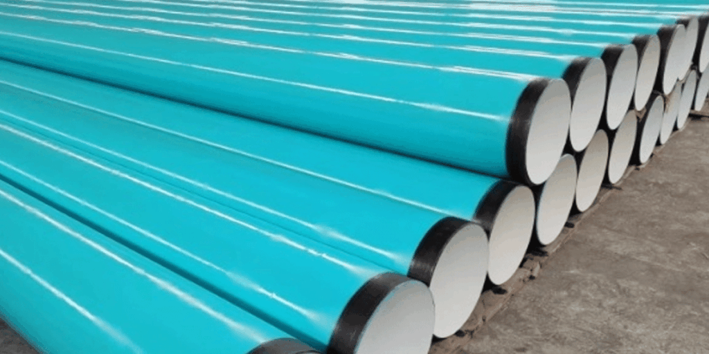
Coating System Names Do Not Define Acceptance
Specifying 3PE, 3LPE or FBE does not define an inspectable purchase requirement. The order must connect the coating system to substrate condition, surface-preparation grade and profile, soluble-salt and dust limits where applicable, minimum and maximum thickness by zone, cutback, holiday-test procedure, repair acceptance, handling protection and release documents.
Failures found after unloading often result from a chain of local deviations rather than bulk material failure: residual scale or contamination, profile outside the coating supplier’s qualified range, thin coverage at seam shoulders or bevel edges, separator pressure during stacking, or repairs released without location and re-test evidence. These risks remain hidden when coating is treated as a finish rather than a controlled process.
An effective inspection framework follows the pipe through five decisions: confirm the coating basis; approve surface preparation; verify application by risk zone; map and re-test repairs; and protect the accepted coating through loading and delivery. Each decision should produce evidence that a receiving inspector can connect to a pipe or bundle.
Select 3PE or FBE Against Installation Risk
Select the system against service exposure, installation method and repair access. Rocky backfill and repeated handling increase mechanical-damage risk; congested urban trench work increases rehandling and joint-work exposure; above-ground sections introduce ultraviolet and temperature considerations. The service fluid alone is not a sufficient selection basis.
Three-layer polyethylene is commonly selected when the order needs both corrosion protection and a mechanically resistant outer layer for handling and burial. Fusion-bonded epoxy systems are used where a bonded epoxy layer, controlled surface preparation and verified holiday testing fit the service and installation plan. Liquid epoxy may suit internal surfaces, fittings or field repairs. The specification should state why the selected system fits the risk, not only its name.
ISO 21809 series, CSA coating standards, DIN requirements, AWWA C213 and owner specifications can define the technical basis, but the purchase order must resolve edition, scope, coating class, test method, sampling, acceptance limits and document format. A standard reference without these order-specific choices leaves important decisions to production.
Surface Preparation, Edge Coverage and Holiday Testing
Surface preparation is the first hold point. Record cleanliness grade, surface profile, dust and contamination checks, abrasive condition and the time between blasting and coating. A low profile can reduce mechanical keying; an excessive profile can leave peaks under-covered. Measurements should be linked to production period, line speed or pipe numbers so an out-of-range result can be contained.
Inspect the pipe body, seam shoulders, bevel edge, cutback transition and repaired areas separately. Average dry film thickness can pass while predictable high-risk zones remain thin. The sampling plan should specify locations, minimum readings and the action required when a local value is below the project limit.
Holiday detection is valid only when test method, voltage, coating thickness, electrode condition, calibration status and travel speed match the governing requirement. Record each indication by pipe number and location, then link repair preparation, material, cure and re-test result to the same entry.
Sampling, Hold Points and Repair Disposition
Inspection frequency should be defined before production, not negotiated after a defect appears. The plan should state how many pipes or production intervals are represented by surface-preparation, thickness and holiday-test records; which changes in abrasive, coating batch, line stop or repair trigger additional checks; and how out-of-range results expand the inspection lot. Without this basis, a list of normal readings does not show whether the lot was adequately sampled.
Hold points should protect steps that cannot be reconstructed later. Examples include approval of the blasted surface before coating, confirmation of cutback before release, review of significant repairs before packing, and acceptance of holiday-test results before loading. Witness points also need advance-notice requirements so the inspector’s absence does not automatically stop production or silently waive the inspection.
Repair disposition should distinguish pinholes, small mechanical damage, repeated defects and damage exposing a larger substrate area. The repair procedure should identify surface preparation, compatible material, environmental limits, cure, thickness verification and holiday re-test. Repeated defects in the same zone should trigger process review rather than independent patching. Any accepted concession should identify the affected pipe and remain in the final release file.
Packing release is the final manufacturing-stage hold point. Verify separators, support width, sling contact, end protection, marking visibility and restraint before loading. Take photographs after the load is secured, because a pre-loading image cannot confirm the condition that will enter transport.
Coated Pipe Inspection Evidence Matrix
| Inspection item | Why it matters | Typical evidence to request |
|---|---|---|
| Surface cleanliness and profile | Controls bonding and local peak coverage. | Blast grade record, profile readings, dust and soluble salt checks. |
| End cutback and edge condition | Reduces coating damage near weld zones and bevels. | Cutback dimension record, end photographs, edge repair notes. |
| Dry film thickness by zone | Average thickness can hide local thin spots. | Body, seam, end and repaired-area readings. |
| Holiday testing | Finds discontinuities before pipe is buried. | Voltage setting, calibration record, defect map, re-test result. |
| Handling and packing | Prevents coating damage after acceptance. | Sling method, separator type, stacking record, loading photographs. |
Coating Inspection Data by Pipe Zone
A useful release package does not need unnecessary volume, but it must preserve traceability. At minimum, connect heat or pipe number, coating batch, production date, surface-preparation record, thickness results, holiday-test record, repair map, cutback check and loading condition. Without that chain, a minor defect can become difficult to allocate after delivery.
For buried pipe, report thickness by zone rather than only an overall range: body, weld seam, end area and repaired area. Separate shop repairs from transit or field repairs. Reconfirm cutback dimensions after final handling when end protection or rework could change them.
Before writing the inspection plan, an ISO, DIN, CSA and GOST coating standards comparison can help match the specified system with the correct reference and test vocabulary. For a multi-layer polyethylene order, 3PE coated steel pipe specifications can help align the commercial description with coating structure, cutback and inspection requirements. Neither resource replaces the project specification; unresolved edition, class and acceptance limits must be closed in the RFQ.
Convert Coating Requirements Into Measurable Acceptance Criteria
Acceptance language should use measurable conditions. Replace ‘good surface preparation’ with the required cleanliness grade, profile range and contamination checks; replace ‘adequate coating thickness’ with zone-specific limits and sampling; replace ‘holiday-free’ with the applicable procedure, voltage basis and re-test requirement.
The release decision should identify which nonconformities permit repair, which require concession and which require rejection. This allows engineering, quality and purchasing teams to compare evidence against the same criteria instead of relying on a coating label or a supplier’s general statement.
Organize the Inspection File by Risk Zone
Department-based files often hide the sequence needed for root-cause review. Blasting may record preparation, production may record thickness, quality may record holiday tests and logistics may record loading. A defect near a pipe end after delivery can be classified only when those records share the same pipe identifier and location reference.
Organize the release file by risk zone: body, seam, cutback and bevel, repair patch and handling contact point. This exposes repeated weak locations that an average value can hide—for example, lower coverage at seam shoulders or recurring damage beside cutbacks.
Photographs should be evidence, not decoration. Capture representative end protection, separator and support placement, each significant repair, pipe marking and loading condition. Include pipe or bundle identification and date so the image can support acceptance or a later claim.
Minimum Coating Inspection Records
Request the smallest record set that can resolve likely disputes. For external coated pipe, that normally means surface preparation, zone-based thickness, holiday testing, cutback dimensions, repairs and handling condition. Additional data should answer a defined risk or contract requirement.
Useful measured values include blast profile by production period, dry film thickness at body and seam locations, cutback at both ends, holiday-test method and voltage basis, defect count, repair dimensions and re-test results. Acceptance ranges must come from the applicable standard and project specification, and the report must be readable by someone who was not present at the yard.
Use an exception log alongside normal inspection results. Record what was found, pipe number and location, disposition, repair method, approver and re-test outcome. The log helps contain recurring defects and prevents repaired nonconformities from disappearing inside summary statistics.
Release Criteria From Coating Yard to Burial
Laboratory properties establish coating capability; release evidence confirms the applied system survived production and handling. The inspection plan should connect material qualification to surface preparation, application, zone-based inspection, repair and transport protection.
That sequence supports concrete decisions: whether mechanical damage risk justifies a three-layer system, whether FBE fits the installation environment, whether field-joint coating needs a dedicated hold point, and whether repaired areas are fit for burial. If any stage lacks evidence, the release file should state the open item rather than treating the coating name as proof.
Coated pipe should be released only when the records can reconstruct the path from substrate preparation to loading. This allows engineering, inspection and receiving teams to evaluate the same risk and prevents unresolved coating assumptions from moving downstream.