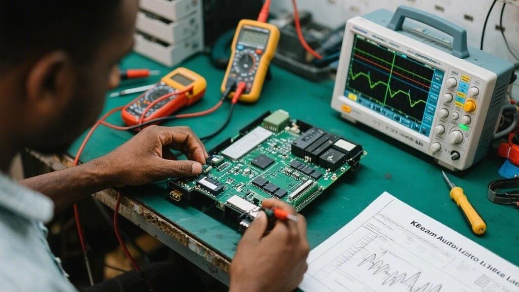
Automotive Engine Control Units (ECUs) represent some of the most sophisticated printed circuit boards in modern vehicles. When original documentation is unavailable or obsolete, engineers must systematically analyze these densely packed assemblies to understand their inner workings. This process reveals critical design decisions that directly impact manufacturability, reliability, and performance. From a PCB engineer’s perspective with years spent reviewing multilayer automotive boards, successful analysis begins with respecting the tight tolerances and complex stackups typical of ECU designs.
Why Perform Detailed Analysis of ECU PCBs?
Professionals and enthusiasts turn to this approach for several compelling reasons rooted in real production environments. Older vehicles often face parts obsolescence, where OEM support has ended. Reconstructing the board enables targeted repairs rather than full unit replacement, preserving functionality in legacy systems. Performance enthusiasts use the insights to optimize fuel maps or sensor response, while R&D teams benchmark competitor layouts to improve future designs.
In manufacturing terms, understanding these boards helps identify common DFM pitfalls early. For instance, inadequate annular ring sizes around vias in high-vibration automotive environments frequently lead to field failures. Reverse engineering highlights such issues, informing better stackup recommendations for new production runs.
Essential Tools for Effective ECU PCB Examination
A well-equipped workspace combines basic inspection tools with advanced diagnostics. A digital multimeter remains foundational for continuity checks and component verification. High-magnification tools, including stereo microscopes, prove indispensable when tracing fine-pitch traces common in HDI-style ECU boards.
High-resolution imaging captures every detail before any disassembly. Soldering stations allow safe component removal for deeper testing, while schematic software turns raw observations into usable diagrams. For multilayer boards, X-ray systems offer non-destructive visibility into buried traces and vias—critical when dealing with 6- or 8-layer constructions typical in engine management systems.
Safe Preparation and Initial Handling
Safety and ESD protection come first. Always disconnect power sources and work on an ESD-safe surface with proper grounding. Carefully open the ECU housing to expose the PCB without stressing connectors or flexing the board, which could crack solder joints or delaminate layers.
Comprehensive Documentation Practices
Begin by photographing both sides under consistent lighting, capturing component markings, trace geometries, and any signs of prior modification. Note via placements and ground plane extents—these elements heavily influence signal integrity and thermal performance in automotive applications.
Annotation of images with layer-specific observations creates a reliable reference set. This step prevents loss of context when moving between physical inspection and digital reconstruction.
Understanding PCB Layout and Functional Blocks
ECU layouts typically divide into clear functional zones: power management with thicker copper pours, the microcontroller core with surrounding decoupling capacitors, sensor input conditioning, and actuator driver circuits. Identifying power rails (commonly 5V or 3.3V logic) and ground planes provides the foundation for further tracing.
Component Identification Techniques
Resistors and capacitors often carry clear markings, but cross-verification with a multimeter is essential in harsh automotive environments where heat cycling can degrade labels. IC part numbers lead to datasheets that reveal pinouts and expected behaviors. Connectors require careful tracing to map sensor and CAN bus interfaces accurately.
In production reviews, we frequently encounter challenges with component footprints that deviate from standard DFM guidelines, such as insufficient clearance for automated optical inspection (AOI).
Reconstructing the Schematic
Start with power and ground distribution, then use continuity testing to map interconnections. Document signal paths methodically, paying special attention to high-speed lines and noise-sensitive areas. Software tools help organize findings into professional schematics.
For complex multilayer designs, X-ray imaging reveals hidden routing that standard visual inspection misses. This mirrors CAM processes where we validate internal layer registration before lamination.
Validation Through Testing
Power up the board cautiously and use an oscilloscope to verify clock signals, sensor inputs, and output waveforms against datasheet expectations. Iterative comparison between measured values and the reconstructed schematic catches mapping errors efficiently.
Comparison of Common ECU PCB Challenges and Manufacturing Solutions
| Issue | Description | DFM Recommendation | Impact on Reverse Engineering |
| Via Placement in High-Vibration Areas | Small annular rings prone to cracking | Minimum 0.15mm annular ring; teardrops on vias | Requires careful X-ray verification of internal connections |
| Inadequate Ground Planes | Increased noise in sensor circuits | Solid copper pours with multiple stitching vias | Trace noise issues during signal analysis |
| Tight Component Spacing | Risk of solder bridges during reflow | Maintain 0.3mm minimum clearance for SMT parts | Complicates desoldering and visual inspection |
| Thermal Management Gaps | Hot spots near power drivers | Copper pours and thermal vias to inner layers | Affects long-term reliability validation |
Challenges and Practical Tips
Multilayer complexity and obscured markings present frequent hurdles. Adopt an incremental approach—master the power section before tackling the processor core. Maintain detailed logs and engage with automotive electronics communities for shared insights.
In factory experience, many issues trace back to stackup deviations or impedance mismatches that become apparent during ECU reverse engineering. Proper documentation and methodical verification overcome most obstacles.
Conclusion
Mastering automotive ECU PCB analysis delivers deep understanding of electronic control systems while highlighting critical manufacturability lessons. By combining careful documentation, systematic tracing, and validation testing with practical DFM awareness, engineers can successfully diagnose, repair, and innovate. Whether addressing obsolete systems or developing next-generation solutions, a disciplined approach grounded in real production realities yields the most reliable outcomes. Applying these techniques responsibly advances both individual projects and broader automotive electronics development.