Delivered does not always mean ready. A process skid can arrive with its vessels, piping and instruments assembled yet leave a project team unable to start the intended process because the plant supplies cooling water under conditions the package designer never received. Elsewhere, a valve might need a command from a control system that nobody included. These integration gaps become visible during commissioning, when each side expects the other to finish the connection.
Buying process skids therefore involves more than choosing components. Useful specifications explain how material, energy and instructions cross the package boundary. Understanding the main skid arrangements helps buyers identify those connections before fabrication, while there is still room to change a layout or assign a missing responsibility.
What a process skid includes, and where it ends
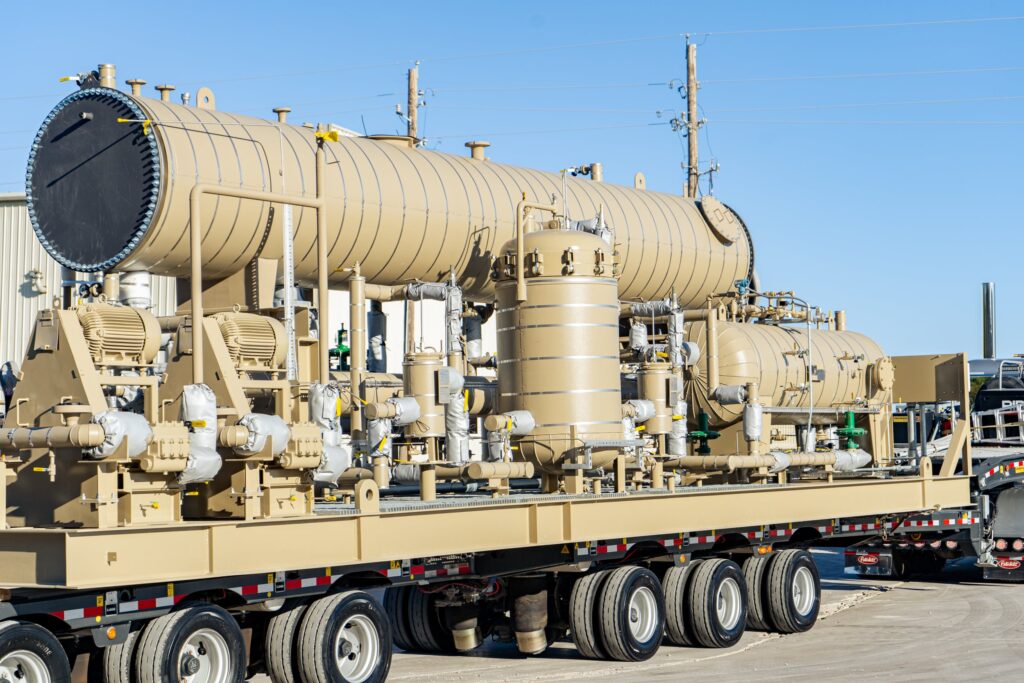
ChannelVessel describes process skids that combine vessels, pumps, valves, piping, instruments and heat equipment. Its homepage also requests process conditions, drawings and interface information when discussing custom fabrication.
Mounting those parts together creates internal connections, but it does not define the surrounding plant, where a feed line may begin outside the frame, a drain may discharge elsewhere, and a control signal may come from a separate panel. Follow those connections beyond the frame. All belong to the functioning process even when they fall outside the supply contract.
Start the specification by describing the operation: what enters, what changes and what leaves. Then draw the supply boundary around the parts being purchased. This separates a useful modular process unit from a loosely assembled list of components. If a supplier proposes moving that boundary, review the affected connections before judging the proposal by price or footprint.
Transfer and dosing arrangements depend on the receiving process
Consider a package intended to move liquid from a source vessel into another operation. Its pump and piping create a flow path, while valves establish where that flow can go. A dosing arrangement adds a requirement to regulate delivery in relation to the receiving process. These functions may look similar on a layout drawing but need different descriptions of expected behavior.
Downstream stoppages expose the boundary. What tells the package to stop, and where does the material remain when the receiving process stops accepting liquid but the transfer package has not yet received an instruction to change its own operating state? Buyers should have the designer explain the intended response instead of assuming that a pump selection answers it. Pressure vessels used within the package also need a duty definition for the conditions they may encounter.
Provide the receiving equipment’s operating states alongside the normal flow requirement. Ask which states are handled inside the package and which require plant instructions. That distinction gives the controls discussion a concrete starting point and prevents the word “automatic” from concealing unfinished integration work.
Heat exchanger skids exchange energy across the boundary
Heating and cooling involve another plant system. Because heat exchangers transfer energy between streams, specifying the process outlet alone leaves an incomplete picture unless the discussion also establishes utility availability and the permitted return conditions at the package boundary. Compactness cannot resolve an undefined utility supply.
The practical boundary appears when the utility behaves differently during startup, normal operation or a plant interruption. Ask the designer to state which supplied utility conditions the proposed arrangement relies on, and how the process should respond when those conditions are absent. Treat the answer as a design input rather than an informal commissioning adjustment.
Trace both sides of the exchanger on the package diagram. Include the location of isolation, drainage and measurement connections in the layout review. A utility connection that fits mechanically can still be unsuitable for the intended operating sequence; matching flange locations is only part of establishing a usable interface.
Reactor packages connect mixing, heat and containment duties
For reactors and other custom process equipment, ChannelVessel requests information about jackets, coils, agitators and internals, alongside pressure, temperature and fluid conditions. Its listed product range also includes heat exchangers and pressure vessels.
Shell details are only part of the package. Mixing arrangements, thermal connections and the route for adding or removing material influence how operators carry out the intended sequence, which therefore needs describing before the team settles the arrangement of surrounding piping and instruments.
Consider the transition from an operating batch to an empty, isolated unit. Which connections remain active? Identify the actions requiring confirmation from the plant rather than inferring the answer from the normal operating drawing. Where a proposed package excludes an agitator, utility circuit or control function, show how the excluded item will connect and who will check the completed arrangement.
A P&ID explains connections that a layout cannot
Piping and instrumentation diagrams, commonly called P&IDs, represent process connections and the associated instruments, whereas layouts show physical positions and available space, allowing reviewers to consider a valve’s intended function alongside its position among surrounding components. Neither replaces the other. An accessible valve on a layout may serve the wrong branch on an outdated P&ID, while a correct schematic can leave that valve difficult to reach.
Use consistent equipment and instrument identities across both documents. Follow a selected operating path from inlet to outlet and check every item encountered. Then follow the routes needed for isolation, drainage and maintenance. Missing connections are easier to discuss when the team can point to a particular path rather than a general concern about completeness.
Control behavior needs explaining separately. Although a symbol shows that an instrument exists, it does not necessarily describe every action triggered by its reading, including actions that rely on instructions exchanged with a control system elsewhere in the plant. Ask who supplies the signal, who uses it and how the required response will be demonstrated before accepting a statement that the controls are included.
Battery limits must describe services as well as flanges
“Battery limits” means the agreed boundary between the package and the surrounding installation. Physical terminations are useful markers, but a boundary schedule should also describe what is expected at each termination. An unspecified utility supply leaves a design assumption unresolved.
Assign responsibility on each side of the connection. For a drain, establish the intended destination and who provides the receiving arrangement. For an electrical or instrument interface, identify the party responsible for the associated design and connection. Do the same for supports or access provisions that depend on the site. Details may be provided by different specialists, but their assumptions must meet at the same boundary.
Changes deserve special attention here. Relocating a nozzle or moving a panel may look like a local adjustment yet affect external piping or cable routes. Before approving it, identify the plant documents that must change as well. Otherwise, fabrication can proceed correctly against a package drawing that no longer matches the installation.
Factory acceptance demonstrates an agreed scope
Factory completion answers a limited question. An assembled skid may be ready to leave the workshop while its site utilities or plant control connections remain unfinished, so acceptance should describe the evidence available at each location and the conditions that cannot be reproduced before shipment.
ASME describes Section VIII Division 1 as covering pressure-vessel design, fabrication, inspection, testing and certification for internal or external pressures exceeding 15 psig. This scope does not certify a particular supplier.
For a complete package, agree the required vessel records separately from demonstrations of package operation. Explain which checks concern workmanship, which concern instruments and which require the actual plant connections. Successful workshop demonstrations should close the checks they genuinely cover, while leaving site-dependent checks clearly assigned. Neither a vessel document nor an impressive demonstration automatically answers every question about the assembled process.
Maintenance access is part of a workable arrangement
Modular construction concentrates equipment in a defined space, making the layout review especially important when operators must reach instruments, isolate piping or remove a component using a maintenance method that needs more room than normal operation does. Check the task, not just the footprint.
Review a proposed maintenance task on the drawing. Ask how the component is isolated, how retained material is handled and where the removed part travels. Compare that path with adjacent piping, structural members and the plant surroundings. Resolve the method with the relevant specialists before treating a small footprint as an advantage.
Access requirements can also change the purchasing boundary. If maintenance depends on a removable pipe section or an external lifting provision, identify it in the supply discussion. Leaving such details until installation invites another integration gap: every supplied component may be present, yet the planned maintenance task remains impractical.
What to settle before comparing process skid quotations
Quotations become easier to compare when the package description follows the process across its boundaries. The public overview of ChannelVessel process equipment is a starting point for discussing the vessel and skid categories; the project documents must then define the actual duty and interfaces.
- Describe normal operation and the transitions that require coordinated plant actions.
- Match the P&ID, layout and interface schedule to the same agreed design.
- Assign utility, piping and control responsibilities at every package boundary.
- Separate factory evidence from checks that depend on the installed system.
- Review access using an actual operation or maintenance task.
Commissioning has a clearer starting point when these decisions accompany the hardware. The value of a process skid lies in connections that have been resolved as a functioning package, with the remaining plant work visible and assigned.