
How to Specify Your Requirements for a Custom RF Cable Assembly

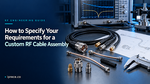
To specify custom RF cable assemblies, describe where they will be used, what electrical performance they must provide, what they must connect, and how they must fit. A complete request also covers environmental conditions, testing, documentation, and order quantity. If the exact cable or connector is unknown, provide your performance targets and installation limits so the manufacturer can recommend a suitable configuration.
RF Cable Assembly Specifications: What Information Should You Provide?
Before sending an RFQ, collect the following RF cable assembly specifications:
- Intended application and connected equipment
- Frequency range and system impedance
- Power level and acceptable signal loss
- Connector type, gender, and orientation at both ends
- Required cable construction or performance
- Finished length, measurement method, and tolerance
- Routing, bend radius, and environmental conditions
- Acceptance criteria, testing, and documentation
- Prototype and production quantities
If some RF cable assembly requirements remain undecided, mark them as open to recommendation rather than leaving the application requirements unclear.
Step1: Define the Application and Electrical Performance
Start by explaining where the assembly will be used—for example, as an antenna feed, inside an RF module, in telecommunications equipment, or on a VNA test bench. This context helps the manufacturer determine which performance requirements actually matter.
Provide the following electrical information:
- Actual operating frequency range
- Characteristic impedance, usually 50 Ω or 75 Ω
- Average and peak power, when applicable
- Maximum insertion loss at a stated frequency
- Maximum VSWR or minimum return loss
Pro Tip: Specify phase matching, time-delay matching, shielding effectiveness, and PIM only when the application depends on them. For example, phase matching may be critical in phased-array or multichannel systems but unnecessary in a basic antenna connection. Avoid descriptions such as “high frequency,” “low loss,” or “high power.” Without frequencies, limits, and units, these terms cannot function as measurable requirements.
Step 2: Specify the Connectors and RF Cable
Define the connector required at each end of the assembly. For connector A and connector B, specify:
- Connector family, such as SMA, N Type, BNC, TNC, or 2.92 mm
- Male or female interface
- Standard or reverse polarity
- Straight or right-angle orientation
- Free-hanging, panel-mount, or bulkhead configuration
Next, provide the approved cable part number or describe the required construction. Your RF cable specifications may call for flexible coax, semi-rigid coax, conformable cable, or a phase-stable cable. Also state any low-loss, repeated-flexing, maximum-diameter, jacket, or shielding requirements.
Pro Tip: If you do not know the correct cable type, provide the frequency range, maximum acceptable loss, available routing space, and required flexibility. The manufacturer can then recommend a cable that meets both the electrical and mechanical requirements.
Step 3: State the Length, Routing, and Mechanical Constraints
Specify the finished assembly length and how it should be measured, such as between the connector reference planes or from end to end. Include the permitted length tolerance, especially when several assemblies must follow the same route.
Also describe the installation:
- Fixed routing or repeated movement
- Minimum available bend radius
- Space around the cable and connectors
- Connector orientation or clocking
- Required strain relief, armoring, or external protection
Pro Tip: A cable that meets its electrical requirements may still fail if it cannot fit the available route or places stress on the connectors. Attach a dimensioned routing drawing for semi-rigid or preformed assemblies. If no drawing exists, provide a marked installation photo showing the route, connection points, and nearby obstructions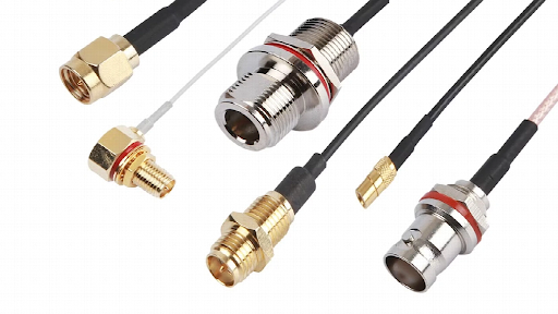
Step 4: Describe the Operating Environment and Applicable Standards
State the conditions the assembly will encounter during operation, storage, and installation. Relevant environmental requirements may include:
- Minimum and maximum temperature
- Moisture or outdoor exposure
- Vibration and mechanical shock
- UV, chemicals, salt spray, or vacuum
- Required IP rating
- Flame-retardant or plenum-rated jacket
Pro Tip: List only standards that apply to the project. RoHS and REACH address restricted substances, while MIL-DTL-17 may apply to the coaxial cable construction. ISO 9001, AS9100, and IATF 16949 describe the manufacturer’s quality-management system; they do not define electrical performance. If environmental testing is required, specify the test method, conditions, duration, and acceptance limits rather than requesting general “environmental compliance.”
Step 5: Define Testing, Acceptance, and Documentation Requirements
Do not request only a “tested cable.” Define which measurements the finished assembly must pass, the frequency range used for testing, and the acceptance limits. The supplier’s vector network analyzer or other equipment must cover the complete specified range.
Depending on the application, required tests may include:
- Insertion loss
- VSWR or return loss
- Phase or time-delay matching
- PIM
- Continuity
- Insulation resistance
Pro Tip: Define the required documentation, such as S-parameters, individual test reports, calibration records, a certificate of conformance, or material traceability. Include these requirements in the original RFQ because additional testing and documentation can affect the manufacturing process, price, and lead time.
Step 6: Provide Production and Delivery Details
Complete the request with the information needed to plan and quote production:
- Prototype and initial production quantities
- Estimated annual volume and expected repeat orders
- Required delivery date
- First-article approval requirements
- Labeling or serialization
- Packaging instructions
Custom Coaxial Cable Assembly Requirements Example
The following example shows how the requirements can be organized in an RFQ:
| Requirement | Specification |
| Application | Repeatable VNA-to-DUT connection |
| Connectors | 2.92 mm male straight to SMA male straight |
| Frequency and impedance | DC–18 GHz, 50 Ω |
| Finished length | 500 mm ±5 mm between mating reference planes |
| Insertion loss | 2.0 dB maximum at 18 GHz |
| VSWR | 1.35:1 maximum across the operating range |
| Cable | Flexible, phase-stable cable |
| Mechanical conditions | Repeated bench handling; 25 mm installed bend radius |
| Environment | Indoor laboratory, 10 °C to 40 °C |
| Testing | S11 and S21 data for each prototype |
| Quantity | 5 prototypes; 100 expected production units |
Attach approved part numbers, routing drawings, or installation photos when available. If any requirement remains undecided, configure your custom RF cable assembly or request an engineering review.






Comment