
How an mpo cable upgrade can fail despite having enough fibers

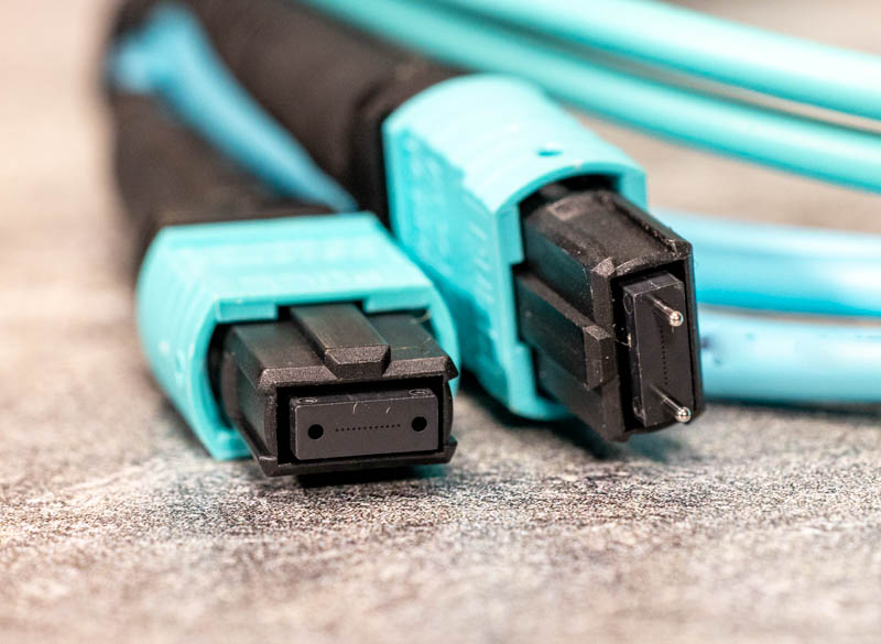
A data center can have spare fibers and still lack a usable path for its next equipment upgrade. The obstacle may be a lane arriving at the wrong receiver, an incompatible interface or connection losses that consume the available budget. Extra fiber capacity cannot settle those questions.
An MPO cable, a fiber optic patch cord and an optical transceiver have to work as a defined channel. For technology managers evaluating an expansion, polarity mismatch and loss budget uncertainty deserve attention before a cable count becomes a claim about future capacity. The upgrade decision starts at the equipment ports and follows the actual path between them.
What an MPO cable changes in a dense rack
A multifiber assembly packages several optical paths into a shared connector. That can make a rack drawing look simpler, but the apparent simplicity hides decisions about which fiber goes where, how the interfaces mate and which fibers the selected equipment actually uses. Treat the assembly as a mapped route.
Start with the installed channel drawing. Mark the equipment port, rack connection, trunk, remote connection and final patching, then compare that route with the proposed equipment interface so that a reused trunk is assessed in the configuration it will actually serve. A warehouse inventory cannot supply this information.
Where it stops: spare capacity in a cable is not a promise of compatibility. Before including reuse savings in the project budget, confirm whether the existing assembly can reach the required ports through an approved arrangement, with enough physical access for installation and later fault isolation.
Fiber count must follow the optical transceiver
Read the optical transceiver interface specification first. Identify the fiber type, connector arrangement, active positions and intended channel limits before choosing a trunk, because equipment with similar front-panel labels may still require different physical connections or use the available fibers differently. Keep the interface drawing beside the cable schedule.
T&S Communications lists 12-fiber single-mode Type A trunk assemblies and a 16-fiber single-mode Type B assembly. These are different catalogue configurations. Their existence shows why “MPO trunk” is an incomplete ordering description; the selected equipment and channel design must decide which configuration belongs in the project, including the intended arrangement at each end of the installed route.
Where it stops: ordering more fibers does not establish that the active positions line up. Require a port-to-port mapping for the proposed assembly before accepting a substitute. A spare fiber only becomes useful capacity when the complete connection arrangement gives it a defined job.
Polarity mismatch survives a successful continuity check
FOA distinguishes straight-through Type A wiring, reversed Type B wiring and pair-reversed Type C wiring. The required result is a transmitter reaching its intended receiver. A cable’s polarity name alone cannot establish that result after modules, adapters and patch leads are added to the channel.
Draw the complete mapping. Mark where any reversal occurs and identify the viewing direction used for each connector drawing, so that a technician reading the far-end drawing does not interpret it as a front view of the near-end interface. Have the installer test the documented mapping.
Where it stops: light reaching the far end only establishes continuity on the path being observed. Polarity mismatch remains possible if that path reaches the wrong position. Save the lane map with the loss results; neither should stand in for the other during acceptance.
The fiber optic patch cord belongs in the migration drawing
Migration plans often describe the backbone thoroughly and leave the rack patching to installation day. That is a weak handoff. A fiber optic patch cord or breakout assembly may decide how the installed trunk reaches the equipment, and an improvised replacement can change the mapping that the design assumed.
List the exact patching arrangement at both ends. Record connector type, polish, pin configuration and cable routing requirements alongside the assembly identifier, then make the same information available to the people who prepare spare stock and respond to service incidents after the migration team has left. Small omissions survive for years in incomplete drawings.
Where it stops: a compatible replacement cannot be selected reliably from length and jacket color alone. Ask for the approved assembly drawing when a supplier proposes an alternative. Resolve the difference before installation rather than leaving a handwritten correction inside a cabinet.
Compare loss grades within an identified configuration
The T&S Communications catalogue lists a 12-fiber single-mode Type A ELITE assembly at 0.35dB maximum and a STANDARD version at 0.75dB maximum. Their fiber designations also differ, so this is a comparison between named catalogue entries, not proof that changing a grade label alone changes every cable by a fixed amount.
Ask what the maximum covers. Establish the tested interface, mating conditions and wavelength before using a component figure in the channel calculation, because a project estimate that silently treats a component limit as the entire installed-path loss can make an unsuitable route look acceptable on paper. Record assumptions beside the calculation.
Where it stops: loss budget uncertainty remains until the complete path is defined. Include the relevant fiber, connections, modules and design allowance, then compare the result with the selected equipment requirements. A lower-loss component may help that calculation; it does not replace it.
MTP vs MPO does not settle interoperability
Searching for “MTP vs MPO” is a useful starting point, but a brand or interface-family label is too broad to approve a migration. Procurement should resolve the exact assembly, the mating interface and the test requirement rather than allowing a familiar name to stand in for those details.
FOA describes the MPO interface’s guide-pin and hole arrangement and notes complications involving keys and angled faces. Those mechanical details affect whether opposing interfaces belong together. A purchasing description therefore needs more than the broad connector name.
Where it stops: neither the most recognizable label nor the lowest quote proves that an offered assembly matches the approved drawing. When evaluating the range from T&S Communications, request configuration-specific documentation and retain it with the purchase record. The same discipline should apply to every proposed supplier.
Test evidence should survive the next equipment change
Specify the handover evidence before ordering. Each identified fiber path should have the required mapping and loss result, with the measurement method and reference arrangement recorded, so that the next upgrade can compare useful evidence instead of commissioning another investigation into an undocumented installation. Keep failed results and corrective actions as well.
Separate component inspection from channel acceptance. Label the test boundaries on the drawing and explain whether the reported result includes the equipment patching or stops at an intermediate outlet. A report without that boundary can be technically accurate and still answer the wrong question.
Where it stops: a passing report for a previous configuration cannot automatically approve a changed route. Reassess the affected path when patching, modules or equipment requirements change. Avoid treating an archived green result as permanent evidence of capacity under every future operating arrangement.
Price the usable channel before approving expansion
Compare quotations on the same scope: the approved trunk, required patching, installation access, test work and documentation. Identify which existing materials can be reused and which depend on unresolved checks. Keep potential reuse savings provisional until the relevant interfaces and performance requirements have been verified.
For the upgrade review, the useful deliverables are a channel drawing, a mapped parts list and an acceptance plan. Assign responsibility for each unresolved item. A cable supplier can confirm an assembly specification; the project still needs someone to confirm that the assembled channel meets the selected equipment’s requirements.
The investment boundary: additional fibers are an asset only when they can serve the intended application. Approve the route that has an explained mapping and an acceptable loss calculation, then preserve the evidence through installation. That gives the next expansion a documented starting point.







Comment