The following article provides a comprehensive exploration of the working principle of a servo motor controller within robotics, integrating practical guidance on servos, motor drivers, Arduino interfacing and considerations for selecting appropriate types of servo motors. It aims to explain how servo motors are used in robotic applications, how servo motor control differs from dc motor and stepper motor approaches, and how controllers and servo drives implement feedback-based motor control to achieve precise positioning and speed regulation in robotic joints and mechanisms.
If you are looking for more information about Servo Motor Supplier – itrustbot go here right away.
What is a servo motor and how does a servo motor work in robotics?
A servo motor is an electromechanical device meant for precise steering of angular or linear position, velocity , and acceleration inside a closed-loop control setup. In robotics, the way a servo motor works is really a mix of a motor shaft, a feedback sensor, and a controller that together make up a servo system able to hold a commanded position or path. Compared with a generic dc motor that just keeps spinning with continuous rotation and needs outside sensing for position data, a servo motor includes feedback, usually from potentiometers, encoders or hall sensors, so the controller can keep checking where things are versus the target. It then forms an error signal, and drives the motor to fix it. This closed-loop behavior is basically what defines how servo motors work: they take position commands from upper-level control systems or microcontrollers, like an Arduino, change those commands into motor speed and torque via the motor driver or servo drive, and then rely on position feedback to remove steady-state error and trim overshoot. The result is tight motion, the kind needed for robotic arms, grippers and mobile platforms.
What are the main components of a servo system (motor, controller, feedback)?
A typical servo system is made up of three main bits : the motor, the controller and the feedback part, and each one does its own important job in servo motor control, even if it sounds simple at first. The motor might be a brushed dc servo motor, a brushless dc motor that is adapted for servo work, or an ac servo motor used in bigger robots. In any case it pushes out mechanical power, through the motor shaft and whatever gear trains or gear motor assemblies are attached. Then there is the controller , which could be embedded inside hobby servos, or it might sit outside as a servo motor controller or a servo drive. It reads the command signal and runs motor control logic like PID, to keep current and voltage under regulation , and that is what ends up controlling motor speed, and also the torque. Finally the feedback element, in many hobby servos it might be a potentiometer, like in the SG90 micro servo motor, while in industrial ac servo motor setups it can be an optical encoder or a resolver. That feedback gives the controller real time information about position or velocity. With those three pieces working together the servo system turns target setpoints into precise motion, while the supporting software and electronics manage the servo motor task via current limiting, damping, and compensation methods, so the system stays stable and can reject disturbances during robotic work.
How does position feedback enable precise servo motor control?
Position feedback makes it possible to run a servo motor precisely, because it closes the sensory loop, where the controller can measure and fix the mismatch between the target position and the real one. Once a command gets sent in, could be from a microcontroller like Arduino or a more advanced control system, the servo driver then changes motor speed and torque until the feedback sensor confirms the motor shaft is at the setpoint you wanted. Meanwhile, the controller keeps calculating the error signal , and it uses control laws. Usually this means a PID algorithm, which then tweaks the voltage or the current that is applied to the motor. Incremental encoders track shaft turns with high-resolution counting, which supports very detailed regulation, and this is great for setups that need repeatability, plus minimal backlash too. Meanwhile potentiometer based feedback, which is often used in typical servo and micro servo units, gives enough angular position information for hobby robotics, but the resolution is lower. Because of feedback, the controller can also add safety functions like overload protection and thermal monitoring, and it can drive more complex motion profiles for coordinated multi joint robotic rigs. That is why servo motors get used a lot when you want precision , and dependable operation.
How does servo motor work differ from dc motor and stepper motor?
The way a servo motor works differs in a fundamental sense from a dc motor and from a stepper motor, at least in how the control architecture is built, how feedback shows up, and where each one fits best. A dc motor usually gives continuous rotation, with the speed being tuned in open-loop by changing the applied voltage or current. Without any feedback signal, a dc motor cannot naturally manage position, and it also cannot properly resist disturbances. Stepper motors instead move in discrete stepwise increments, with control often done open-loop in many real setups. They can deliver strong low-speed torque and straightforward position control even when feedback is absent, as long as you stay within the torque limits. Yet, when speeds rise, missed steps and resonance become noticeable problems. A servo motor, in contrast, runs closed-loop using feedback, so it can hold accurate position, produce smoother motion, and respond well when the load shifts. Also, digital servo motors and modern servo drives add more elaborate control patterns, like velocity and torque control loops, so you get higher bandwidth and improved efficiency compared to basic dc or stepper systems. In robotics, the decision between servo, dc and stepper usually comes down to what you need for accuracy, speed, torque, and overall system complexity, where servo systems are typically chosen for high-performance robotic joints that must follow a precise path over time.
What types of servo motors and servos are used in robotics?
Robotics use leverages a range of servo motors and servos, from small hobby micro servo units to industrial ac servo motors, that are used for precision automation. The different types of servo motors usually get grouped into hobby servos (like the well known sg90 micro servo motor), standard servos and high torque servo motor versions. There are also digital servo motor models, plus heavy-duty ac servo motor systems, with encoder based feedback and more advanced servo drives. Each one tries to answer a different need: micro servos are great for small scale robots and for UAV control surfaces, standard servos tend to work for general purpose robotic joints and even grippers. Meanwhile high torque servos, and servo metal gear units bring in the muscle needed for robotic manipulators and load bearing assemblies. For industrial jobs, people often choose ac servo motors or dc servo motor setups, plus dedicated servo drives and built in cooling, so they can handle continuous duty cycles and higher speed motor speed demands. Picking the right thing among these types of servo motors mainly depends on torque, precision, durability, the control bandwidth, and the control architecture you selected inside the overall robotics control system.
What are the differences between micro servo, standard servo and high torque servo motor?
Micro servos, standard servos, and high torque servo motors aren’t just different in one aspect, it is more like a set of small changes that add up, mainly in physical size, how much twisting force they can handle, the gear train layout and the way they’re meant to be used. For instance a micro servo, for example the sg90 micro servo motor, is small and light, and it is built for low torque jobs like tiny robotic fingers or model aircraft control surfaces; it usually runs from limited current, and it often relies on plastic gears. Standard servos give you a middle ground between size and torque for everyday robotics needs, with plastic or metal gearing used depending on the particular design. Then high torque servo motors push the winding size up, adjust gearing ratios, and sometimes even switch to gear motor configurations, so they can produce higher torque for heavy joints, grippers, and actuation parts; these often come with metal gear servo internals and bigger housings, partly so heat can escape more easily. The mechanical build itself, whether it is plastic gearing or a servo metal gear assembly, ends up shaping how long it lasts, the amount of backlash you notice, and the long-term dependability. Because of that, these points matter a lot when you’re adding servos into robot designs that have to keep working steadily under load.
When to choose digital servo motor vs analog servo drive?
Picking digital servo motor solutions over analog servo drives really comes down to how much performance is needed, how precise the control must be, and how complex the whole system can be. Digital servos usually have an onboard microcontroller and run those high frequency control loops, so they tend to respond quicker, give more fine grained position resolution, and unlock extra options like programmable endpoints, plus torque limiting that feels more controlled. They are often favored when you need strong dynamic behavior, low jitter, and firmware level tuning, especially in robotics competitions and precision grippers where small changes matter.
Analog servo drives are more straightforward and may be enough for low cost setups or less demanding tasks, where basic PWM based control and only modest bandwidth will meet the job. In industrial automation, and more advanced robotic systems, you will also see dedicated servo drives for both dc servo motor and ac servo motor setups, and these bring reliable current limiting, sensible thermal management, multi loop PID structures, and communication interfaces that plug into the broader robot control system.
So, designers really end up balancing trade-offs around cost, latency and capability when deciding between digital servo motor architectures and analog servo drive approaches.
How do metal gear servo, gear motor and 25t servo compare for durability?
Durability in servos is often a matter of gear material and how the whole layout is built, and sometimes it depends on the motor mount too. A metal gear servo plus gear motor assembly generally gives better wear resistance and higher load support than plastic-geared versions; as a result, the chance of stripped gears after a jolt, or during heavy loading, is usually lower. That’s why these metal gear setups work well for robotic joints that see demanding motion.
The 25t servo, which usually points to servo horn splines that match standard servo horns and is often matched with metal or reinforced gear trains, is a middle choice between mechanical compatibility and torque ability. Gear motor arrangements that use planetary gears or spur metal gears tend to extend service life even more, and they also help with continuous torque delivery without fading as quickly.
That said, the design still needs to account for lubrication, backlash control, and the effects of repeated load cycles. While metal gears improve durability in most situations, they can also pass stronger shock into bearings and they need good alignment with the motor torque and control system settings. Otherwise premature wear can show up in the motor shaft or inside the gearbox assembly.
How does a servo motor controller or servo motor driver function?
A servo motor controller, or sometimes called a servo motor driver , acts as that intermediary layer where command signals from a control system or a microcontroller get turned into regulated electrical power for the motor, but also it does feedback processing, so closed loop control can actually run. The servo drive will take in position and or velocity setpoints , which may come as PWM pulses from an Arduino or as serial commands in industrial setups. After that it works out what current is needed to hit the requested motor speed and torque, using internal regulation loops that stay active continuously.
Some core tasks are PWM generation , current sensing with limiting, applying PID or more advanced control strategies, plus handling safety interlocks like overcurrent protection and a thermal shutdown sequence. In practice, by modulating the output applied to the motor windings , the servo controller can govern speed and position with good precision, so the shaft tracks the commanded path, while reacting to disturbances, changing loads , and those pesky nonlinearities that show up in mechanical transmissions used in robotics.
What is the role of a motor controller and servo drive in motor control?
The motor controller with the servo drive, together, carry out motor control by supplying power electronics, sensing, and the kind of algorithmic processing needed to regulate how the machine moves. The motor controller usually means the higher level logic that sends the setpoints around, aligns multiple axes, and does motion planning inside the control stack. Meanwhile, the servo drive is the power plus control stage that sits right by the motor, running the faster control loops, doing current regulation, and translating those setpoints into high frequency PWM waveforms, or into inverter outputs for ac motors. Together they keep motor speed torque and position in bounds, they take feedback from encoders and other sensors, and they keep things safe using current limiting and thermal monitoring. When you have robots that need coordinated multi joint movement, the motor controller ties in several servo drives and syncs their timing so the kinematic and dynamic limits required by the robot’s control system design are respected.
PWM signals coming from an Arduino or a motor driver steer where a servo goes by putting the target angle into tiny changes of pulse width, while the pulses keep repeating at a steady rate. For most hobby servos that repetition is around 50 Hz, so the servo expects a new pulse every 20 ms or so, and the internal logic pays attention to how long that pulse stays high. The width is read in milliseconds, and that number maps to the position, like a kind of angular setpoint. Once the servo detects the incoming timing it drives its motor, and the built in controller keeps moving until the feedback sensing says the requested spot is reached.
With more advanced servo motor drivers you may not always rely only on the classic “servo PWM” position meaning. Instead the PWM can be used to modulate the motor voltage, or it can be mixed with direction cues plus encoder information, so you get velocity control, torque control, or a tighter motion loop. When you work with an Arduino, libraries usually take a simple command and turn it into the right PWM timing automatically. Meanwhile, dedicated servo drivers and servo drives deal with the power stage and the closed loop actuation details needed, especially if you are commanding both standard and higher torque servo motors in robotics builds.
Common features you’ll find in a servo motor controller meant for robotics include things like current limiting, PID style control loops, thermal protection, and some sort of encoder or other feedback interfaces. There are also usually configurable gain parameters, and a communication path that fits into the wider control system, so the robot can talk to it in a predictable way.
Current limiting matters because it helps prevent motor damage and also protects the power electronics when the load spikes or when the mechanism stalls. Then the PID loops, often arranged in a cascade setup like position loop feeding velocity loop, and sometimes even torque control underneath, give you the stability and responsiveness robotics really needs. Extra items may show up too, like programmable motion profiles, position capture, braking behavior, regeneration handling, and safety interlocks. Together these features support reliable repeatable operation, and they help the servo motor deliver precise speed and torque behavior in intricate robot tasks while maintaining longevity in more complex control architectures.
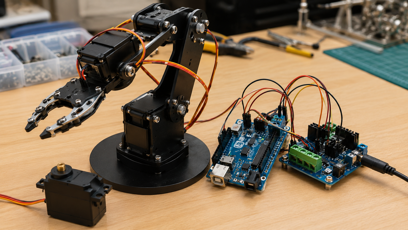
How to control servos with Arduino: setup and common problems
With Arduino, controlling servos means you need to think about wiring that is correct, choosing the right power supply or maybe a motor driver, and then using a code approach plus libraries that really let you send PWM commands and, when possible, deal with feedback. When people use hobby servos such as a micro servo or a standard servo , the usual wiring has the signal wire going to a PWM-capable Arduino pin, while the servo itself is powered from an external supply that stays stable and can deliver the higher surge current during stall conditions or fast movement. If the project shifts toward more demanding high torque servo motor setups, or you want a servo motor driver configuration , then a dedicated controller or a full servo drive is needed so it can manage the current and perform closed loop control. In many Arduino servo builds, you might see jitter from electrical noise, or when grounding is not handled well, also overheating shows up if the servo is pushed too hard, or if it is undersized for what the mechanism demands. Another common issue is insufficient torque because the chosen servo is not a match for the mechanical requirements, so resolving it often comes down to proper motor selection, sizing the supply, improving signal quality, and using the right kind of servo for the job.
How to wire an Arduino servo and select the right power supply or motor driver?
To wire an Arduino servo, you connect the servo signal wire to a PWM-capable digital pin on the Arduino , then link the servo ground back to the Arduino ground so there is a shared reference. After that, give the servo its own power, using a supply that can handle the stall current plus the quick transient demands that show up during motion. If you plan to power several servos, you will usually need a separate regulated power line, or a battery pack with enough current headroom.
When you move to larger servos, or when you are combining DC servo motor or AC servo motor approaches, include a suitable motor driver or a dedicated servo drive between the Arduino and the motor. This helps with power conversion , current control, feedback paths, and safety functions. Drivers meant for hobby servos typically take a basic PWM input, while industrial servo drives often expect encoder feedback and use a digital bus conversation. Picking the right power supply or motor driver depends on the servo voltage, its current profile, the peak power during fast movements, and what control interface your robotic setup needs for the selected servo motors .
What Arduino libraries and code patterns implement servo motor control and PID?
Common Arduino libraries and usual code approaches for servo motor control include the built in Servo library, for basic PWM based servos, which makes it easier to pass angular commands to micro servos and also to typical standard servos and many digital servos that use PWM interfaces. When people need feedback oriented control and PID routines, libraries like PID_v1 help with closed loop logic, so you can tweak proportional, integral, and derivative gains to get the reaction you expect. More involved builds often stack encoder reading utilities, add smoothing filters, and use state machines to support trajectory following, interpolation steps, and multi axis coordination.
Writing dependable routines also means adding safety checks, including current level and temperature monitoring tasks. You may also use interrupt driven PWM or encoder handling, to keep timing deterministic, which matters for quick responsive servo control in robotics projects.
How to troubleshoot jitter, overheating, and insufficient torque in Arduino servo projects?
Troubleshooting jitter, overheating and not enough torque needs a kind of systematic look at power, signal, plus the mechanical side. Jitter usually comes from noisy power rails, messy grounding, or clashes in PWM timing, and fixing it means you add decoupling capacitors , confirm a single shared ground, use a dedicated PWM timer, and consider smoothing the control line while also filtering the feedback sensors.
Overheating can happen if the system keeps stalling for too long , if the servo is too small and it works beyond the rated torque, or if airflow is just not there; to reduce heat you typically choose a higher rated high torque servo motor, lower the duty cycle, make cooling better, and set current limiting through the motor controller.
Insufficient torque points to a mismatch between the chosen servo and what the load actually needs, for example an sg90 micro servo motor or a regular standard servo that is being asked to do more than it can. Swapping to a gear motor, a metal gear servo, or a bigger high torque servo usually helps, but you should also verify gear ratios, check mechanical advantage, and remember the trade-offs in motor speed as well as control precision.
How do servo systems compare to stepper motor and AC/induction motor solutions?
Servo systems, stepper motors and ac/induction motor solutions show different strengths, and limits in robotics, mostly because control precision cost torque traits and integration difficulty aren’t the same. Servo systems give closed loop position plus velocity control, with high bandwidth and good rejection of disturbances, so they work well for hinged robotic joints where fast motion response and exactness really matter. Stepper motors give open loop positional control and are simpler plus less expensive for low to medium performance work, but they can drop steps when the load rises, also they often hit resonance at certain rotational speeds. AC servo motor and induction motor setups are common in industrial use, they tend to deliver strong power and better efficiency during nonstop operation, and with the right servo drives they can be used in robotics needing lots of torque and speed. Still their physical size, expense, and control complexity often block them from small robotics projects. In the end picking one of these motor classes comes down to trade offs in system design, balancing cost against the needed motor control finesse and the real operating environment.
A servo system is more preferred than a stepper or a dc motor when the task needs strong dynamic behavior, repeatable placement, and good regulation even while the load changes. you typically want smooth motion profiles, plus closed-loop correction that reduces the chance of accumulated position drift. That’s why multi-axis coordination in articulated robots, high-speed pick and place work, and situations where torque needs to be held tightly, tend to lean toward servo motor control. Also, when the robotic job has unpredictable loads, requires high acceleration, or must hold positional accuracy despite bumps and external disturbances, the servo drive and its controller give you the needed capability. Open-loop stepper systems and plain dc motor setups cannot reliably match that without extra sensing and added complexity.
Yes, an AC servo motor or an induction motor can be used in small robotics applications, but the choice depends on what you need for control accuracy. An AC servo motor usually fits better when tight position control and fast response are important, because it uses feedback such as an encoder. An induction motor can be used when the design can tolerate more advanced control tuning or when precise positioning is not the main requirement, but it generally needs a suitable drive and control strategy to work efficiently at small scales.
AC servo motors and induction motors are usually better for industrial scale systems but they can still make sense in small robotics, especially when high power and continuous duty are needed; though, their add on part integration often ends up needing more advanced servo drives, larger mechanical interfaces , and more power handling than most hobby grade or compact robotic setups can really fit. On the other hand, AC servo motor solutions tend to give really strong speed-torque behavior, plus accurate encoder feedback if you use the right servo drive combo, but for small robots , dc servo motors, gear motor stacks and micro servo units often feel like a more workable compromise for size, cost, and control simplicity, particularly with microcontrollers like Arduino.
Trade offs between servo and stepper usually land in a few places, cost, control precision, speed, and torque. Servos generally come with closed-loop position or velocity feedback, so they can hit commands more precisely and resist load changes better, while steppers are typically open-loop and can lose steps if the load ramps up too quickly. In raw control feel, steppers are often easier to drive with pulse signals and they can be cheaper per axis, but they usually need more careful tuning for microstepping, acceleration ramps, and resonance, and their effective holding torque can drop at higher speeds. For torque, servos can deliver more consistent torque across speed ranges in many practical setups, while stepper torque is more tied to motor size and drive current and can fall off as speed increases. In speed, steppers can reach decent speeds but they often show performance limits earlier due to resonance and the step rate ceiling, whereas servos can be pushed higher with proper tuning and drive selection.
The trade-offs between servo and stepper systems includes cost, control precision, speed, and torque characteristics: steppers tend to be less expensive and easier to command in open loop, especially when losing a step is acceptable, yet they have weaker motion dynamics and they can show resonance issues plus noticeable torque drop when the rotational speeds climb. Servo systems are usually pricier because you have servo drives, encoders, and closed-loop controllers, but they give better command precision, more usable torque at speed, and stronger rejection of outside disturbances. This combination leads to smoother movement and higher throughput in robotics. Designers usually have to weigh these things budget limits, required motor control accuracy, available space, and target motor speed, before choosing a stepper or a servo motor architecture for a specific robotic job.
What are common servo motor applications and selection criteria in robotics?
In robotics, common servo motor uses show up everywhere, joint actuation in humanoid platforms and industrial manipulators is one of the main ones, along with precision grippers, pan tilt camera mounts, steering mechanisms for autonomous vehicles, and even hobbyist robotic arms. The way people pick the right servo usually starts with torque, speed, physical size, signal feedback resolution, and how well it survives harsh conditions; engineers end up weighing the continuous torque vs peak torque demands, the highest allowable motor speed, the space it must fit in, and what gear ratio they actually need. They also decide what kind of feedback and what level of resolution is required so the control loop can reach the accuracy targets.
After that, there are extra practical things like gear material choices, for example a metal gear servo is picked for durability, thermal handling, expected duty cycles, and whether it works cleanly with the servo motor controller or motor driver they already have. In the end the selected servo has to match the bigger control system layout and the integration plan, so the robot can keep behaving reliably across its intended missions.
How to choose the right servo motor for robotic joints and grippers, focusing on torque, speed, and size?
Choosing the right servo motor for robotic joints and grippers, kind of, is mostly about working through the required torque in worst case loading, then figuring out the necessary angular velocity and acceleration for what the task actually does. After that you pick a motor size plus a gear ratio that really hits those numbers, while still leaving reasonable thermal and mechanical margins , not too tight. You also have to think about whether the application demands continuous torque versus brief peak torque, because they are not interchangeable in real life. Gear efficiency matters too, and so does backlash, since it directly affects control precision, and yes that pushes back into how the control loop bandwidth has to be set. Lots of teams prototype using standard servos or gear motor builds, and later step up to a higher torque servo motor, or an ac servo motor option when more responsiveness or strength is required , also making sure it is compatible with the servo drive and the overall control system in the robot.
For safety and reliability, which factors really matter, like overload protection strategies, and the specific gear type?
When you pick a servo, safety and reliability factors matter, and not just in a straight line. Overload protection, current limiting, and thermal monitoring in the motor controller are big ones, also keep an eye on the gear type , because metal gearing tends to last longer. Backlash minimization matters too, and for critical axes adding redundancy can prevent unpleasant failures. Then, the IP rating should match the environment you plan for, dust, moisture, and similar exposure.
The overload protection handled by the servo driver helps keep the motor and gearbox from getting damaged when there are stalls or collisions. At the same time gear selection influences long-term dependability , and it can shift how often maintenance is needed. On top of that, the servo motor controller needs to work cleanly with the sensors used for feedback. If the control system also includes solid fault handling, you get safer operation, and the robotic system service life usually extends as well.
How do servo motor controllers integrate into larger robot control systems and control system architecture?
Servo motor controllers end up in bigger robot control systems by kinda plugging into higher-level motion planners, real-time controllers, and sensor fusion layers. They take incoming setpoints and then report back status, usually via standardized communication protocols or dedicated bus links, you know. In a multi-axis robot, each servo drive can be set to accept position commands or torque commands from one central motor controller, or from a real-time controller that keeps the whole thing coordinated. That coordination covers trajectory timing, it also enforces kinematic limits and deals with collision avoidance in the background. The overall control system architecture has to keep everything synchronized, maintain safety interlocks, and aggregate feedback without lag. At the same time it must provide consistent timing determinism, so closed-loop performance stays stable. Integration also means setting up clear interfaces for calibration, diagnostics, and tuning of PID gains, so the servo motor controller and the broader control system behave cohesively, and deliver the precision and responsiveness modern robotics applications demand.