Pin headers are one of the most flexible and adaptable components used to connect a cable/module or board-to-board interface on a printed circuit board. This guide covers connector basics, types of pin headers, and practical considerations when selecting a header to connect peripherals or stack expansion boards. From a simple 2.54 mm breakaway header strip on a breadboard to a boxed, shrouded PCB connector with IDC ribbon cable, reliable integration across Arduino, Raspberry Pi, and custom circuit board designs hinges on understanding spacing, the number of pins, and the mechanical format.For more in-depth information you should view from Pin Header Connector Manufacturer&Supplier – Soulin
Pin Header Connector Beginnings
Header connectors serve a modular interface function between a PCB and external systems, merging male pin and female socket elements organized in single or double-row configurations. The 2.54 mm (0.1 inch) increments are customary and breadboard friendly, facilitating prototyping and promoting the widely used 40 pin stacking header ecosystems in GPIO expansions. Other alternatives consist of a slight male header with right angle for compact, low-profile panel mount, surface mount for automated assembly, and boxed heads with shrouded IDC ribbon cables. The correct header type selection revolves around the pin counts, mechanical orientation, and the type of connection involved between board-to-board, cable, or socket-to-pin.
What is a Pin Header?
Pin headers can be found as connectors on printed circuit boards. They are made of a plastic piece with pins from the top and are spaced by 2.54 mm. They can be bought in strips and can be cut at any length. It is possible to create a custom length to obtain a 40-pins connector. Pin headers can also be bought in surface mount or right angle versions. They can be bought in stacking versions which allow a connection of multiple boards at once. These connector headers are soldered into the circuit board to allow for interconnections.
The use of Pin Headers in PCB Design
The use of pin headers increases design flexibility with I/O and serviceability. During the prototyping stage of design, a 2.54 mm male header allows the designer to make jumper connections quickly to a breadboard, and in the production stage a shrouded box header allows for strain relief on a ribbon cable. Designers have to choose between single-row and double-row configurations to maximize their space and pin routing, and they have to choose between using a right-angle or vertical design based on their physical enclosure and panel mount placements. The consistent pin assignments and GPIO header designs on Raspberry Pi and Arduino computers increase design flow, allowing stack expansion and linkage to other devices without additional redesign.
Basic concepts of connectors
Basic connector concepts involve their mechanical design, electrical value, and their connection point. Common spacing for connectors is 0.1 inches (2.54 mm). Other considerations while designing for connectors include the number of pins, header types (male header, female socket, or board stacking header), and orientation (straight, right-angle, or right-angle male header). For soldering, connectors can use through-hole or surface mount. For connectors using ribbon cable, a box header with a shroud fits over the ribbon cable. To solder a module, the module must engage with the male header pins on female pin headers. 40 pin strips and breakaway headers are used for quick design customization, while panel mount connectors simplify and standardize external connections.
The Varieties of Header Connectors
Pin style, spacing, mechanical format, and mating interface all highlight the diversity of header connectors. Most pin header connectors have 2.54 mm (0.1 in) spacing to fit breadboards, and other pin-compatible accessories, and popular gpio systems like Arduino and Raspberry Pi. For most configurations, designers can select single row or 2 row layouts, vertical or right-angle orientations, and can use through-hole or surface mount terminations to fit their pcb and panel mount configuration. Other types of connectors include breakaway header strip segments for prototyping, stacking headers for board-to-board stac assemblies, and box headers with shrouds for IDC ribbon cables. The number of pins and other fundamentals like the connector’s current rating and mechanical durability limit the choices that can be made to find a header.
Male Header Versus Female Header
Male headers have protruding pins and are designed to be soldered onto PCBs. They are typically used to create breakaway headers for prototype systems. Female headers, known as female sockets, have a recessed connector and are designed to mate to a male header. They are often used on modules to create a removable connection to accessories. Female header modules are common on prototype devices. Male headers are used for breadboarding, and for interconnecting PCBs and devices. Female sockets are preferred for protective interfaces, for alignment, and in systems where frequent connections are made, such as in Arduino, Raspberry Pi, or custom devices.
Explaining Different Kinds of Pin Headers
When it comes to pin headers form factors, there are type spacings, row arrangements, orientations, as well as terminations. The most common type, 2.54 mm (0.1 inch) pitch headers are either single or double row with 40 pin lengths or 40 pin breakaways for custom pin lengths. As for placements, there is both a straight and right angle option, as well as right-angle male headers for low profile routing. Lead finish type varies, and can be either for through-hole or surface-mount for compatibility with assembly procedures. Other common types are stacking headers for added height or parts intended for panel mount. All of these headers are designed to provide reliable mechanical strength and the retention of plugs, with compatible sockets or plugs for reliable interconnects on the circuit board.
| Category | Details |
| Spacing & Formats | 2.54 mm (0.1) standard; single-row or two-row; 40-pin and 40-pin breakaway lengths |
| Orientation & Termination | Straight and right-angle orientations (including right-angle male headers); through-hole and surface-mount termination |
| Specialized Forms | Stacking headers for elevated board-to-board stacks; panel-mount friendly parts |
| Design Priorities | Mechanical robustness, solder reliability, and cable or socket compatibility for durable interconnects |
Understanding Box Headers and IDC Connectors
A box header is a shrouded PCB connector that guides and keys an IDC ribbon cable for error-proof mating. The shroud provides polarization so the ribbon cable aligns with the header pin array, minimizing misinsertion on a PCB. Commonly at 2.54 mm spacing in two rows, the box header interfaces with an IDC cable that is terminated via insulation displacement, enabling fast production. Variants include right-angle and vertical styles, with options for surface mount or through-hole solder. Designers select the number of pins to match GPIO pinouts or module buses, ensuring a reliable header to connect board-to-board or cable harnesses on a circuit board.
| Feature | Details |
| Pitch and Row Format | 2.54 mm spacing, two rows |
| Cable Interface | IDC ribbon cable, insulation displacement termination |
| Mounting Options | Right-angle or vertical; surface mount or through-hole |
| Use Case | Match pin count to GPIO or module bus; board-to-board or harness connections |
Specifications and Dimensions
The first step in defining a pin header connector is determining spacing, pin count, then defining a mechanical format to use, with the most prevalent standard being 2.54 mm, or 0.1 inches, as used on breadboard prototypes, Arduino shields, and Raspberry Pi GPIO headers. To suit the layout of the printed circuit board, designers must choose from single-row or dual-row arrays, straight or right-angle orientations, and through-hole or surface-mount terminations. The plastic base, the length of the exposed male pin, the shroud, and the box header will have an impact on clearance, fit in the panel mount, and cable mating. To ensure reliable header connecting and board-to-cable-assemblies, the connector basics are straightforward.
Overview of 2.54 mm Pitch Connectors
2.54 mm pitch correlates to the center-to-center distance for each of the headers pin, which in turns promotes compatibility of header connectors, female header sockets, and IDC ribbon cable assemblies. This 0.1 standard is compatible to breakaway header strips, 40 pin and 40 pin stacking configurations and header stacking ecosystems typical of Arduino and Raspberry Pi. Uniform spacing streamlines breadboard usage with jumper cables and ensures that a male pin header will interface with a female socket or socket header from different suppliers. When box header components are deployed, the shroud provides keyed alignment while preserving the 2.54mm pitch matrix on the pcb connector for reliable solder joint and refilterable connection.
Common Dimensions in Header Connectors
Typical measurements include number of rows, connector height, and connector size. The width of the plastic base comes in single row and double row options, spanning the size of the plastic base. The male header pins extend above the plastic base to fit into the socket and underneath the plastic base to solder to the printed circuit board. Clips retain pins in sockets, and several standard exposed male pins fit solder Cups and female headers in cables. Both board stack and board-space height configure long tail pins. A box header adds enclosure height and height and clearance polarization. For edge access a right angle and right angle connector has a 90° male pin bend. For compact PCB routing, surface mount connectors have shortened tail length.
The verification activity for male pin measurement involves the checking pitch first; which means you take the first male pin, and visually and physically, on the caliper, check the separation between one pin to the other determining if it measures 2.54. If it does, keep counting the number of pins to see if it is a 40 pin breakaway, custom length header strip. Afterwards, measure the plastic above board length’s base engagement with the male pin to the tip of the pin, and to confirm you have enough engagement in the header. After you are done you will have to measure the male pin length soldered in base; to determine if surface mount is a valid directly below the base tail, solder depth, and through holes pin in surface mount. For the right-angled male header parts, do the same verification to above, but also measure the length of the horizontal leg for clearance. When also on a box header, do not underestimate the importance of the overall height measurement; as you may have to guarantee if fit for a ribbon cable, shroud header, coming up.
| Measurement | What to Check |
| Pitch | Center-to-center spacing should read 2.54 mm on calipers |
| Pin Count | Confirm 40 pin, breakaway, or custom length header strip |
| Above-board Length | From plastic base to pin tip for engagement with a female header/socket |
| Tail Length | Below the base to validate through-hole depth or SMT compatibility |
| Right-angle Details | Horizontal leg length and clearance |
| Shrouded/Box Header | Overall height for ribbon cable fit and panel spacing |
Utilization of Pin Header Connectors
The versatility of pin header connectors makes it ideal for various application fields like prototyping, education, and production electronics where reliable header connections are required for modules and board interfaces. With the assistance of the 2.54 mm spacing, designers strategically position the male header pins on the printed circuit board (PCB) so that they align with the female header, or female socket for, removable connections. The various header options, including IDC, box header with shroud, and breakaway header strips, accommodate ribbon cable harnesses, compact surface mount assemblies, and panel mount feedthroughs. Whether using one or two rows at right or vertical angles, selecting the pin quantity and style of the header can ensure powerful integration on any PCB.
Raspberry Pi and Arduino Applications
Raspberry Pi and Arduino ecosystems utilize standardized 0.1 spacing and 40-pin or shield-aligned pin formats to maximize system modularity. The boards have male headers that expose gpio to connect to sensors and modules, and shields or HATs have female pin headers that offer a socketed interface to stack on top of the header assemblies. Developers often use a breakaway header strip to tailor the pin count and configure to single or double row arrangements. Right-angle male header variants are useful for low-profile casings, while box header components create a signal path to an IDC ribbon cable for off-board peripherals. These components enable rapid prototyping to production on the circuit board.
Incorporating with a Breadboard
In prototyping, the 2.54 mm pitch architecture is central to a breadboard. This enables a male pin header to connect different modules and jumper wires during rapid prototyping. For fast settings, breakaway headers trimmed to 40 pins or custom lengths are used to form flexible interconnects between a PCB and the prototyping area. For signal and power rails, or compact two-row buses, engineers can route GPIO from an Arduino or Raspberry Pi to the breadboard over a short ribbon cable, or by direct pin entry. The plastic base keeps the header pins aligned, and soldered terminations on an adjacent PCB ensure the assembly stands up to repeated handling from prototype to finished product.
Attachments of Ribbon Cables
Ribbon cables utilize a box header that includes a shroud covering the header pins (which protects the header pins) to secure the connection. An IDC (Insulation Displacement Connector) termination provides quick assembly, with consistent electrical performance, making it suited to panel mount harness and internal link (Pcb to Pcb) applications. Choosing the appropriate number of pins with the standard 2.54 mm pitch allows compatibility with off the shelf cable assemblies. Vertical and right angle configurations accommodate space constraints in an enclosure (like a box) and female socket headers on detachable daughterboards facilitate board-to-board stacking. Connector basics, like contact [insert word], strain relief, and alignment keys preserve signal integrity and reliability across (general purpose input output) gpio buses and higher density path two row interfaces on a circuit board.
Choosing the Right Pin Header Connector
Choosing the appropriate pin header connector entails consideration of mechanical, electrical, and assembly requirements. Starting with pitch, which is usually 0.1 or 2.54 mm, then determining pin count, followed by single row vs dual row, followed by straight vs right angle orientation which is most suitable. Assess if a female header or female socket is preferable for serviceability, or if a male header is suitable for direct wire or module insertion. For a connection by cable, a box header with a shroud accommodates IDC ribbon cable, whereas stacking header options allow for board-to-board stacking configurations. Decide between surface mount and through-hole soldering based on where the connector will be positioned on the assembly flow, and connector attributes such as current rating and required durability.
Factors in the Choice of Male Headers
Confirm compatibility between the male header and the corresponding socket and pcb connector footprint. Check the 2.54mm pitch, solder tail length, and height of the male header pins to see if they will mate reliably with the female pin headers. Depending on the routing density and gpio mapping, choose the number of pins, single, 40 pin, or a custom breakaway length and whether a single or double row is needed. Vertical and right angle should be considered for enclosure fitting and panel mount clearance purposes. During assembly, the material and plating choice will influence how much wear insertion will cause, and the height of the plastic base will influence clearance. Ensure a cable interfaces alignment with the box header or IDC systems and ribbon cable strain relief.
Deciding on Right Angle Headers vs Stacking Headers
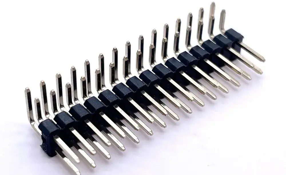
When it comes to scenarios where edge access and low-profile assemblies are crucial, right-angle male headers are preferable, because the pin on the header is horizontal, minimizing the depth of the case. Furthermore, right-angle male headers are most suitable when a panel mount or side-entry of a ribbon cable is required. On the other hand, stacking header components are for when vertical connections are necessary, because the header pins are extended vertically, allowing for a second board to be plugged in (e.g., a board stacked on top of an Arduino or Raspberry Pi HAT). This is often done to access additional pin functionality (e.g., GPIO). The choice of which is most appropriate relies on a number of factors, such as how much height is available in the enclosure, how frequently the signals will be accessed, and how much mechanical support is desired. When selecting between a single and double row, consider the robustness of the solder joints and the functionality of the socket and pin engagement. Stacking headers also work well in scenarios where some modules have a pin header while others have a socket header, because it provides a good balance between modularity and serviceability.
Features of Breakaway Headers
The general-purpose header strips are supplied as 40-pin lengths at 0.1” spacing. They are easily customized by separating each segment along the score line so that any desired number of pins can be retained. Engineers separate that section to make single row jumpers or to assemble two row arrays mounted on a printed circuit board. Soldering a male pin header strip makes it a permanent fixture, or it can be used with a female socket to make a removable module for breadboard prototypes. This type of breakaway header increases efficiency across design iterations by supporting a variety of pin headers, both straight and right angled, and simplifies inventory. They work with box headers and IDC connectors through adapter boards to provide a versatile header for cable connections and stacked assemblies.