
From Prototype to Production: How DFM Reduces Cost and Risk in CNC Machining

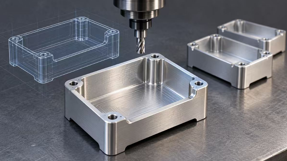
A CNC-machined prototype can fit correctly and pass functional testing while still being expensive to reproduce. Consider an aluminum housing with deep pockets, thin walls, and tightly toleranced surfaces throughout. A machinist may produce one acceptable part using cautious cuts and repeated checks. Those same requirements become recurring costs in a batch.
Many CNC manufacturing problems originate in the design, before cutting begins. Design for Manufacturability (DFM) reviews geometry, specifications, and production requirements while changes are still manageable. It connects what a part must do with how it will be machined, held, finished, and inspected.
Why CNC Costs Are Often Determined Before Machining Begins
Material removal is only part of the cost. A supplier must also program toolpaths, select cutters, prepare workholding, establish inspection methods, and arrange finishing.
Geometry influences each decision. A narrow pocket can require a small cutter and longer machining time. Features on several faces can require repeated repositioning. A demanding surface finish may add finishing passes or a separate process.
Part size and stock availability matter too. A small projection may force the entire component to start from a larger blank, increasing material waste and roughing time.
These decisions also affect lead time. Special tooling, custom fixtures, and difficult inspection requirements can delay production even when machine capacity is available.
Tolerances: Tighter Is Not Always Better
Tolerances should reflect fit and function. A bearing seat, locating hole, or sealing interface may need close control. An exterior surface with generous clearance may not.
Unnecessarily tight limits can require additional finishing passes, tool offsets, controlled measurement conditions, or secondary operations. They also leave less room for variation from tool wear, temperature, and workpiece movement, increasing the risk of rejection.
For a mounting plate, the relationship between locating holes may be critical while the outside profile needs only clearance. Applying the same tight tolerance to both adds work without improving the assembly.
Review tolerance stacks before relaxing individual dimensions. Identify functional datums, specify geometric controls where needed, and define an appropriate general tolerance for other features. Critical requirements should also have an agreed inspection method: a dimension that is difficult to measure can create uncertainty at acceptance.
Designing Features for Efficient CNC Machining
Several common features deserve attention during DFM:
- Deep pockets: Long tool reach reduces rigidity and complicates chip evacuation. A shallower cavity, wider opening, or revised pocket layout may allow more stable cutting.
- Thin walls: Cutting and clamping forces can deflect slender sections. Where function permits, increase thickness, shorten unsupported spans, or add supporting ribs.
- Internal corner radii: A rotating end mill leaves a radius at a pocket’s vertical internal corners. Larger allowable radii accommodate stronger cutters. For a square mating component, localized corner relief may provide clearance without forcing the whole pocket to use a tiny tool.
- Small holes: Small, deep holes increase the demands on tooling and chip removal. Use common diameters where suitable, and specify only the depth and thread engagement the application requires.
- Tool accessibility: Check clearance for the cutter, shank, and holder. A reachable cutting edge does not guarantee that the holder can pass surrounding features.
Complex contours and undercuts also deserve scrutiny. If they serve no functional purpose, simplifying them can remove special tooling or extra orientations. Review how each feature will be deburred and inspected as well as cut. Hidden burrs and inaccessible measurement surfaces can turn an otherwise machinable design into a production problem.
Material Selection and Machinability
Material selection changes cutting conditions, tool life, achievable surface quality, and the way a part behaves during machining.
For an enclosure or lightly loaded bracket, 6061 aluminum often provides useful strength and good machinability. 7075 aluminum can suit a more highly loaded component, but its additional strength should answer an actual design requirement. Both are machinable; grade, temper, stock availability, and finishing requirements belong in the comparison.
Stainless steel requires grade-specific planning. Austenitic grades such as 304 and 316 can work-harden, making tool engagement and cutting conditions important. A design with long, slender features can compound those machining difficulties.
Titanium alloys create greater demands on heat control and tooling than common aluminum alloys. Deep cavities and delicate sections therefore deserve especially careful review.
Engineering plastics introduce different concerns. Acetal may suit a low-friction component, while nylon’s moisture absorption can affect fit. Thermal expansion and machining heat must also be considered when specifying close dimensions.
Compare the finished component’s performance and total production cost. A lower stock price can be outweighed by longer cycles, tool consumption, or dimensional instability.
Reducing Setups Through Better Part Design
Each time a part is unclamped and repositioned, the process needs reliable location, secure workholding, and verification. Additional setups add handling time and can introduce variation between related features.
Where practical, orient critical holes and mating surfaces so they can be machined together. Provide accessible datum surfaces and enough material for secure clamping. Datums should represent how the part functions in its assembly and support a workable machining and inspection plan.
A part with features accessible from a few directions may be economical on a 3-axis mill. Indexed 3+2 machining can expose angled faces without repeated manual repositioning; simultaneous 5-axis machining can support more complex surfaces.
The appropriate choice depends on geometry, quantity, and the available process. Higher machine rates may be offset by fewer setups, but that tradeoff should be evaluated for the actual component.
Designing for Surface Finishing
Finishing requirements should appear in the design package before quoting. They affect dimensions, appearance, processing sequence, and inspection.
Anodizing converts the aluminum surface into an oxide layer that extends into and above the original surface. External dimensions can grow and hole diameters can decrease. The dimensional change depends on the alloy and process, so confirm allowances with the finisher rather than assuming one universal value.
Bearing seats, threads, and electrical contact areas may need masking. State whether critical dimensions apply before or after finishing.
Bead blasting changes texture, while polishing removes material and can alter edges or small features. Identify cosmetic faces and protect functional surfaces when needed. An approved appearance sample can make expectations clearer than a finish name alone.
Plating, painting, and other coatings also require dimensional and process planning. Include finishing lead time and inspection of the completed surface in the production schedule.
Moving From Prototype to Production
A typical progression is:
Prototype machining → DFM feedback → Design revision → Process optimization → Production planning → Quality inspection → Repeatable batch production.
DFM should begin before the first prototype and continue as physical testing reveals what the design needs. Prototype results establish fit and function; manufacturing feedback identifies which requirements make production difficult.
A review with a precision CNC machining partner can help the engineering team resolve tolerance, tooling, material, and finishing questions before the production design is released.
A successful prototype may have involved hand deburring, repeated measurement, or adjustments by an experienced operator. Those steps need review before scaling. The production process should define workholding, machining sequence, tool replacement criteria, and inspection checkpoints.
For the housing example, a revision might retain critical mounting interfaces while increasing pocket radii and improving clamping access. Engineering should verify that those changes preserve performance.
Use a pilot batch to evaluate the intended process. First-article inspection verifies initial conformance; subsequent checks assess variation across the run. Keep models, drawings, programs, and inspection records tied to the approved revision, and revalidate affected features after changes.
A Practical DFM Checklist Before Sending Parts for Machining
Before requesting a quote or releasing production drawings, ask:
- Are tolerances tighter than necessary? Connect each critical limit to function or an assembly requirement.
- Can cutting tools access all features? Include holder clearance, chip removal, deburring, and inspection access.
- Are internal corner radii practical? Confirm suitable cutter sizes and clearance for mating parts.
- Are walls too thin? Review unsupported height, material stiffness, and clamping loads.
- Can the number of setups be reduced? Group related features where practical and provide usable datums.
- Is the selected material appropriate? Specify grade and condition, then check performance and machinability.
- Have finishing requirements been considered? Define masking, appearance, and final dimensional acceptance.
- Are critical dimensions clearly identified? Agree on measurement methods and required inspection records.
- Is the design suitable for repeat production? Check workholding, tool wear, revision control, and pilot-batch results.
Conclusion
Early DFM decisions give teams practical ways to reduce machining complexity, control costs, and shorten lead times. They also reduce avoidable rework by resolving questions about tolerances, access, material behavior, and finishing before production starts. The result is a part whose functional requirements are supported by a defined, repeatable manufacturing process, with fewer problems left for operators and inspectors to solve during each batch.






Comment