ESP8266
The ESP8266 NodeMCU is a chip developed by Espress if.
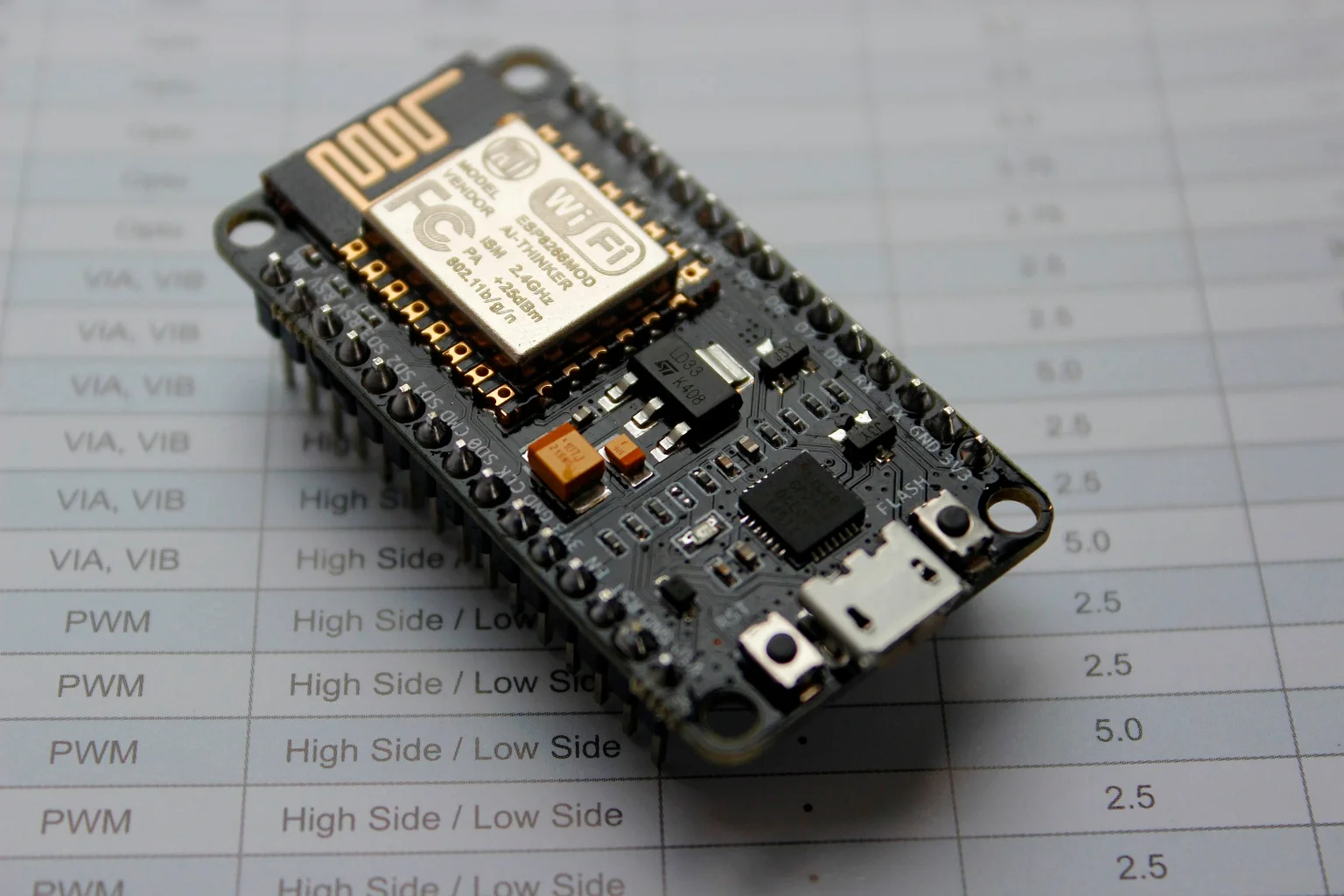
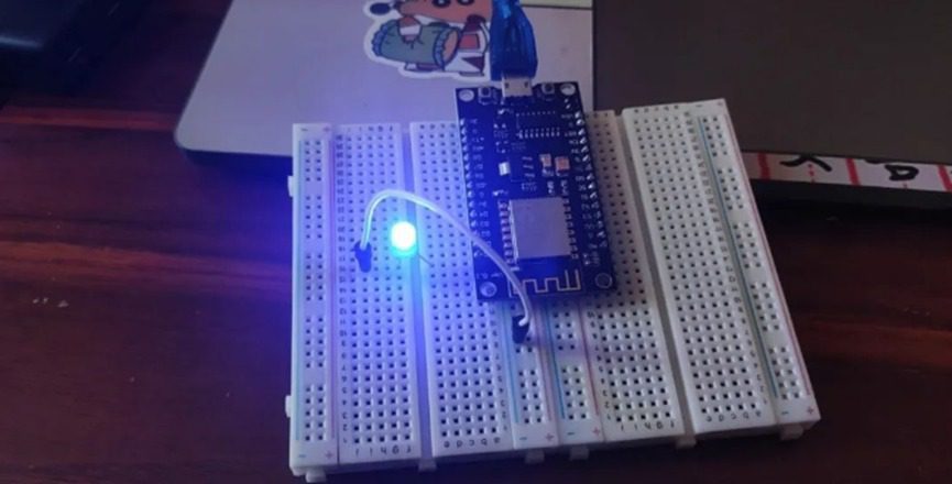
Generally, a development board that looks like the one below, equipped with the ESP8266 chip, is called an ESP8266 NodeMCU.
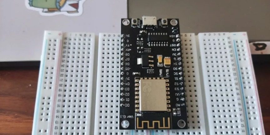
Although there may be slight variations, any chip labeled ESP8266 is fine. Because anyone can make their own ESP8266 NodeMCU board with an ESP8266 chip.
The ESP8266 integrates WiFi internally, so it can function as a WiFi module (I’ve done it, collecting data with STM32, then transmitting it to ESP8266 via serial communication, and then uploading the data to the server with ESP8266), or as a standalone microcontroller.
Let’s now start writing a program for ESP8266 NodeMCU using Arduino IDE. (Some basic knowledge of microcontrollers is required, otherwise some terms may be confusing.)
Arduino IDE Environment Setup
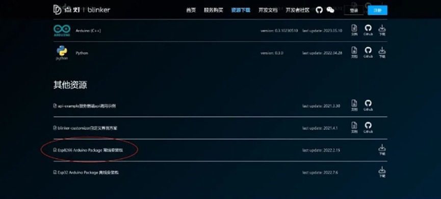
To write programs for ESP8266 NodeMCU using Arduino IDE, we need the ESP8266 development board package, which we can find in the offline installation package on the official website of Electronic Lamp Technology.
The package also includes resources for ESP32.
After clicking the download button, you will be redirected to the Chinese Arduino website, where you can follow the steps to download. You will get an .exe file, which you can directly execute.
Then, in the Arduino IDE, follow the selections below (I can’t take screenshots because the options disappear when I use the shortcut keys, so I’ll have to describe it instead).
GPIO
To learn about a chip, let’s become masters of lights first.
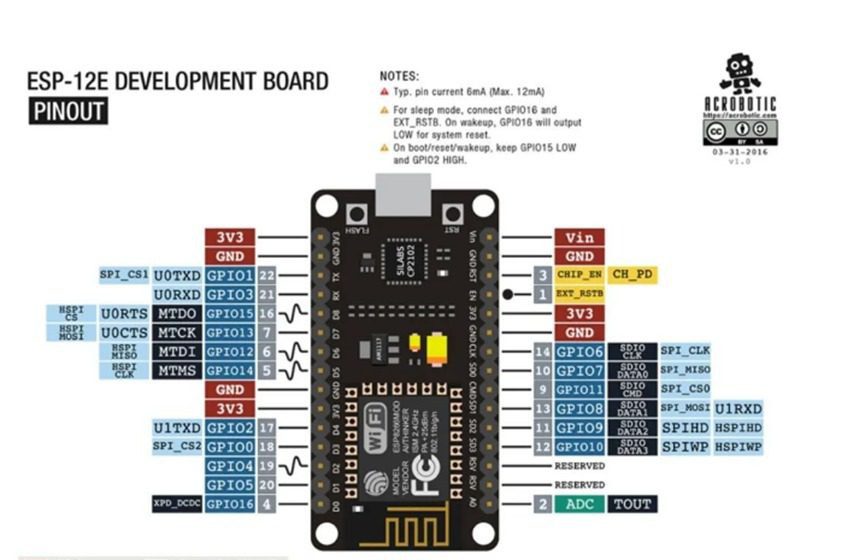
Actually, we have very few GPIO ports available on ESP8266 NodeMCU.
Although it looks like there are many GPIO ports, we cannot use the GPIO ports on the right side (except for special purposes), as they are used to control internal storage units. Just remember that the GPIO ports on the same side as A0 cannot be used.
Then, among the GPIO ports on the left side, GPIO1 and GPIO3 are used for serial communication and are generally not used for other purposes, so the available GPIO ports are actually quite limited.
Let’s light up an LED.
Blinking LED
Configuring GPIO Mode
pinMode(uint8_t pin, uint8_t mode);
The first parameter can be directly filled with the label on the ESP8266 NodeMCU development board, such as “D0”, or you can enter a number. For example, D0 is actually GPIO16, so entering the number 16 is also acceptable.
The second parameter configures the mode. In simple terms, we use three types: OUTPUT, INPUT, and INPUT_PULLUP, which are used for output, input, and pull-up input, respectively. Although there are more modes that can be configured, these three are the most commonly used.
Digital Output
digitalWrite(uint8_t pin, uint8_t val);
The first parameter specifies the GPIO port, same as above.
The second parameter is a direct numeric value; 1 is for high level and 0 is for low level.
Lighting Up LED
void setup() {
// put your setup code here, to run once:
pinMode(D0, OUTPUT); // equivalent to pinMode(16, OUTPUT);
scss
Copy code
digitalWrite(D0, 1); // equivalent to digitalWrite(16, 1)
}
void loop() {
// put your main code here, to run repeatedly:
}
In case some friends are not familiar with this code format (because 51 and 32 are writing main functions), let me explain a bit. The setup function is for configuring things and is only executed once, while the loop function contains the code that will be executed repeatedly, similar to the while(1) loop in 51 or 32 code.
So, we first configure the GPIO port, then output a high level, and then connect the LED to achieve the operation of lighting up the LED.
Delay Function
delay(unsigned long ms);
Enter a number to delay for the corresponding number of milliseconds.
delayMicroseconds(unsigned int us);
This is for microsecond delay.
Blinking LED
With the delay function, we can make the LED blink.
void setup() {
// put your setup code here, to run once:
pinMode(D0, OUTPUT);
}
void loop() {
// put your main code here, to run repeatedly:
digitalWrite(D0, 1);
delay(1000);
digitalWrite(D0, 0);
delay(1000);
}
Simply output high level and low level alternately.
Of course, the above code looks too cumbersome, so we have a more concise way.
Digital Reading
digitalRead(uint8_t pin);
With this function, we can read the input level of the corresponding GPIO port.
We just need to make the output level of the GPIO port different from the input level.
Blinking LED 2.0
void setup() {
// put your setup code here, to run once:
pinMode(D0, OUTPUT);
}
void loop() {
// put your main code here, to run repeatedly:
digitalWrite(D0, !digitalRead(D0));
delay(1000);
}
You may be confused why we can read when the GPIO port is configured as an output.
I’ve tested it, and it works. When the GPIO port is in output mode, what is actually read is its own output. If you want to read the input from other modules, you still need to configure it as an input (INPUT) mode, otherwise the read data may be incorrect, or even affect the module to be connected.
Timing Function
First, you need to include <Ticker.h>.
Then define a Ticker type object, and the name cannot be “time” (learned it the hard way).
Call the member function of this object to complete the timing operation.
Scheduled Execution
attach()
The first parameter of this member function is filled with an integer, indicating the timing in seconds.
The second parameter is filled with the function name, which can have at most one integer parameter. So, the function will be executed every number of seconds specified in the first parameter.
The third parameter, if the function filled in earlier has no parameters, then the third position can be left empty, otherwise the third parameter is the parameter passed to the function when it’s called.
This function can be called multiple times, but only the last one will take effect.
For millisecond-level timing, use the following member function.
attach_ms()
Cancel Timing
detach()
This member function has no parameters. After calling it, the previous timing will be canceled.
Timer Function
If you only need to call it once and don’t need looping timing, you can use the timer function, which has the same parameters as the timing function and will only be called once.
once()
once_ms()
It should be noted that each Ticker object can only have one task at the same time.
Blinking LED 3.0
#include <Ticker.h>
Ticker t0;
Ticker t1;
void test(int flag){
digitalWrite(D0, !digitalRead(D0));
}
void setup() {
// put your setup code here, to run once:
pinMode(D0, OUTPUT);
t0.attach(1, test, 1);
t1.once(10, &{
t0
Additionally, some other information I found mentioned that there are functions to modify the PWM output frequency. However, after testing with a passive buzzer, I found that these functions didn’t seem to work, and I couldn’t find the reason why.
One of these functions is as follows. You can try it with your own board, just in case it works:
“`cpp
analogWriteFreq(uint32_t freq);
“`
External Interrupts
External Interrupt Configuration
“`cpp
attachInterrupt(uint8_t pin, void (*)(), int mode);
“`
The first parameter specifies the GPIO pin, but unlike before, here you need to use `digitalPinToInterrupt()` to wrap the GPIO pin. This indicates that the GPIO pin is used for external interrupts, and note that D0 cannot be used for this purpose.
The second parameter is a function without parameters or return value. This function will be called when an external interrupt is triggered. When defining the function, you need to include `ICACHE_RAM_ATTR` at the beginning of the function.
The third parameter specifies the conditions for triggering the external interrupt. There are three options: `RISING`, `FALLING`, and `CHANGE`, representing rising edge, falling edge, and both rising and falling edges, respectively.
For specific details, you can refer to the code below.
Disabling Interrupts
“`cpp
detachInterrupt(uint8_t pin);
“`
If we need a GPIO pin to stop triggering external interrupts, we use this function. Here, the parameter is directly written without using the `digitalPinToInterrupt()` function.
Controlling LED with a Switch
“`cpp
int count = 0;
ICACHE_RAM_ATTR void test() {
digitalWrite(D0, !digitalRead(D0));
if (++count >= 10) detachInterrupt(D1);
}
void setup() {
pinMode(D0, OUTPUT);
pinMode(D1, INPUT_PULLUP);
attachInterrupt(digitalPinToInterrupt(D1), test, RISING);
}
void loop() {
// Main code
}
“`
Here, D0 is set as output mode, D1 as input mode, and external interrupt on rising edge of D1. Each time it triggers, it toggles the level of D0. After ten times, it detaches the interrupt on D1.
Serial Communication
After connecting ESP8266 NodeMCU to the computer via a data cable, you can directly use serial communication with the computer.
Arduino IDE has a built-in serial monitor, located in the upper right corner of the page. Clicking on it will bring up the serial monitor at the bottom of the page, where you can easily send and receive data.
Serial Initialization
“`cpp
Serial.begin(unsigned long baud);
“`
There is only one initialization function, but there are five overloaded versions. The most commonly used one is shown above, where we specify the baud rate, and the default settings are 8 data bits, 1 stop bit, and no parity bit.
Outputting Data
There are many functions for outputting data. Here, I’ll briefly introduce a few that I often use.
**write**
“`cpp
Serial.write();
“`
This function has twelve overloaded versions. Generally, when we need to output raw data in hexadecimal format, we use this function.
**print & println & printf**
“`cpp
Serial.print();
Serial.println();
Serial.printf();
“`
These three output text format, so they are commonly used for debugging information.
– `print`: Normal output.
– `println`: Similar to `print`, but adds a newline character (`\r\n`) at the end.
– `printf`: Used for formatted output, similar to how we use it in C language.
Reading Data
There are also many functions for reading data. Here, I’ll briefly explain a few that I personally use frequently.
**read**
“`cpp
Serial.read()
“`
This function has two overloaded versions. Let me explain both:
– The first version doesn’t have any parameters. It simply reads one byte and returns it.
– The second version looks like this:
“`cpp
Serial.read(char *buffer, size_t size);
“`
It reads the number of data specified by the second parameter into the buffer provided by the first parameter. However, if the size of the second parameter is larger than the available data to be read, it will only read the available amount of data and return the actual number of bytes read.
**readString**
“`cpp
Serial.readString()
“`
This function reads data and returns it as a String type.
Checking for Data Availability
If we want to read data, we first need to know if there is any data available. How do we know when there is data available? We use the following function:
“`cpp
Serial.available()
“`
It returns an `int` value to indicate whether there is data available to be read. But we can treat its return value as a `bool` type.
Serial Echo Experiment
Now that we understand these functions, we can use ESP8266 NodeMCU for serial communication.
The following code is an echo experiment. When data is received, it is echoed back unchanged. This is
—
The effect is also very good. This is my own mobile hotspot that I connected to. I deliberately disconnected the interrupt once, but it could reconnect again.
MQTT
Now that we have connected the ESP8266 NodeMCU development board to the internet, we are just one step away from mastering the ESP8266.
Microcontroller + Internet = IoT. Speaking of the Internet of Things, the unavoidable communication protocol is MQTT. Of course, HTTP/HTTPS can also be used, and there are corresponding libraries for ESP8266 for that purpose. However, we’ll focus on how to communicate using MQTT.
Environment Configuration
First, we need to use the PubSubClient library. So we need to download it.
Download it from the following website:
https://www.arduino.cc/reference/en/libraries/pubsubclient/
After downloading the zip file from this website, import it into the Arduino IDE.
Then include `<PubSubClient.h>`.
And with this library, we also need to include `<ESP8266WiFi.h>`.
Yes, that’s the library we used to connect to Wi-Fi.
Initialization
First, we need to create two objects.
“`cpp
WiFiClient wc;
PubSubClient pc(wc);
“`
The first object of type `WiFiClient` requires the `ESP8266WiFi` library.
The second object of type `PubSubClient` requires the `PubSubClient` library, and we need to pass a `WiFiClient` type object to initialize it.
It’s that simple.
Settings
Secondly, we can start setting the MQTT server and port.
“`cpp
pc.setServer(“xx.xx.xx.xx”, 1883);
“`
There are free public MQTT servers that we can use directly. You can find them online. As for the port, MQTT is basically 1883.
It’s that simple.
Connection
Thirdly, we can start connecting.
“`cpp
pc.connect(WiFi.macAddress().c_str());
“`
We need to pass the ID used to connect to the MQTT server, which cannot be the same as the IDs of other devices connected to the MQTT server at the same time. Generally, I use the physical address of the device, so it won’t overlap with others. There are other overloaded versions where you can set other information needed to connect to the MQTT server, but I won’t demonstrate them here.
It will return whether the connection is successful.
It’s that simple.
Publish Topic Message
After connecting successfully, we can subscribe and publish.
“`cpp
pc.publish(topic, data);
“`
In the first parameter, fill in the topic name to be published. In the second parameter, fill in the content to be published.
It’s that simple.
Subscribe to Topic
“`cpp
pc.subscribe(topic);
“`
Fill in the topic name to subscribe to, and that’s it.
It’s that simple.
But after subscribing, we’re not done yet. Where do we go to retrieve the subscribed messages?
Subscribe Callback Function
“`cpp
pc.setCallback(getMQTT);
“`
Fill in the name of the callback function. When a message is received on the subscribed topic, this callback function will be automatically called.
So how does this function know which topic the message came from and what the message is?
That’s because this callback function has a fixed parameter format.
“`cpp
void getMQTT(char* topic, byte* payload, unsigned int length)
“`
I arbitrarily named this function, and you can too. The key is that the parameter types after the function name must be consistent.
The first one is the topic name from which the message came.
The second is the actual message data.
The third is the length of the message.
One more thing, we need to periodically report to the MQTT server that we’re still alive, meaning sending a message to tell MQTT that we’re alive. This is called heartbeat information. We can set the heartbeat interval before connecting to the MQTT server.
“`cpp
pc.setKeepAlive(n);
“`
If not set, it defaults to 15 seconds. If we don’t send heartbeat information within 15 seconds, MQTT will think we’re dead, and we won’t receive subscribed messages. So, we need to send heartbeat information frequently within the heartbeat interval.
There’s also the following function:
“`cpp
pc.loop();
“`
At the same time, we also have a function to determine whether we are connected to the MQTT server. If we are connected, we can send heartbeat information. If disconnected, we can reconnect.
“`cpp
pc.connected();
“`
So far, we can handle MQTT. I believe the following code segment can help you deepen your understanding. It’s best for everyone to try it out yourself.
“`cpp
#include <ESP8266WiFi.h>
#include <PubSubClient.h>
const char* WIFINAME = “xxx”; // WIFI name
const char* WIFIPASSWORD = “xxx”; // WIFI password
// Parameter one is WIFI name, parameter two is WIFI password, parameter three is the maximum waiting time set
void connectWifi(const char* wifiName, const char* wifiPassword, uint8_t waitTime) {
WiFi.mode(WIFI_STA); // Set to wireless terminal mode
WiFi.disconnect(); // Clear configuration cache
WiFi.begin(wifiName, wifiPassword); // Start connecting
uint8_t count = 0;
while (WiFi.status() != WL_CONNECTED) { // Wait until connected
delay(1000);
Serial.printf(“connect WIFI…%ds\r\n”, ++count);
if (count >= waitTime) { // Exit if exceeding the set waiting time
Serial.println(“connect WIFI fail”);
return;
}
}
// Connection successful, print the connected WIFI name and local IP
Serial.printf(“connect WIFI %s success, local IP is %s\r\n”, WiFi.SSID().c_str(), WiFi.localIP().toString().c_str());
}
void getMQTT(char* topic, byte* payload, unsigned int length) {
Serial.printf(“get data from %s\r\n”, topic); // Output debugging information to know which topic the message came from
for (unsigned int i = 0; i < length; ++i) { // Read each byte of the message
Serial.print((char)payload[i]); // Read it as text, or remove (char) to read it in hexadecimal
}
Serial.println();
}
WiFiClient wc;
PubSubClient pc(wc);
uint8_t connectMQTT() {
if (WiFi.status() != WL_CONNECTED) return -1; // Return directly if not connected to the network
pc.setServer(“xx.xx.xx.xx”, 1883); // Set MQTT server IP address and port (usually fixed as 1883)
if (!pc.connect(WiFi.macAddress().c_str())) { // Connect to MQTT server using physical address as ID
Serial.println(“connect MQTT fail”);
return -1;
}
String topic = WiFi.macAddress() + “-receive”; // Subscribe to a topic, topic name is physical address + “-receive”
pc.subscribe(topic.c_str());
pc.setCallback(getMQTT); // Bind subscription callback function
Serial.println(“connect MQTT success”);
return 0;
}
void setup() {
// put your setup code here