To sculpt the polarization of a light beam—the direction in which its electric field oscillates—opticians rely on wave plates. These unassuming, flat crystals are masters of controlled delay. Their secret lies in birefringence, a property where the material has two distinct optical axes. Light polarized along one axis, called the “fast axis,” travels through slightly quicker than its counterpart aligned with the perpendicular “slow axis”. This carefully engineered speed difference creates a phase shift, or retardance, between the two wave components. The most common retardance values are precisely a quarter or half of the light’s wavelength (λ/4, λ/2), giving these plates their defining names and their power to transform one polarization state into another. This article will explore what a quarter-wave plate and a half-wave plate are, how these two fundamental types work, and guide their practical application.
What is a Quarter-Wave Plate (λ/4)?
This fundamental property of birefringence finds its first key application in the quarter-wave plate (λ/4). In essence, this device is a master of changing the fundamental character of polarized light. Its primary “magic” lies in converting straightforward linear polarization into a spiraling circular one. This transformation occurs when linearly polarized light strikes the plate at a precise 45-degree angle to its axes. At this moment, the crystal splits the beam into two perpendicular components traveling at different speeds. By introducing a delay of exactly one-quarter of a wavelength, it shifts these components a quarter-cycle out of step. When they recombine on exit, their electric fields no longer point in a single line. Instead, one lags behind the other just enough to make the tip of the combined field vector rotate in a perfect circle over time, creating circularly polarized light. The process is reversible; feeding circular light into a QWP yields a linear output. If the input angle isn’t exactly 45 degrees, the result is elliptical polarization—a more general, oval-shaped rotation.
What is a Half-Wave Plate (λ/2)?
While the quarter-wave plate changes the type of polarization, its half-wave cousin performs a more direct maneuver: it rotates linear polarization. Think of it as a precise tool for steering the plane in which light’s electric field oscillates.
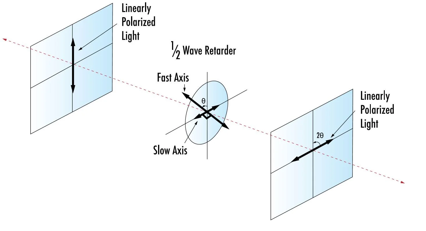
The mechanism hinges on a deeper delay. When linear light enters, its components along the fast and slow axes are again separated. This time, however, the plate introduces a half-wavelength (λ/2) retardance. This delay is equivalent to a full half-cycle shift, which fundamentally inverts the phase of one component relative to the other. When they recombine, the effect is not a spiraling circle, but a clean geometric reflection. The output polarization vector appears mirrored across the plate’s optical axes.
This leads to a powerful and simple rule. The final polarization direction is rotated by exactly twice the angle between the initial linear polarization and the wave plate’s axis. For instance, aligning the input at 30 degrees to the axis results in an output neatly turned to 60 degrees. This predictable control makes the HWP indispensable for adjusting laser beam polarization without altering its fundamental character.
Where and How Are Wave Plates Used?
The distinct abilities of quarter and half-wave plates make them workhorses across optics. A quarter-wave plate is fundamental in systems that create or analyze circular light. You’ll find it in optical isolators protecting lasers, in ellipsometers measuring thin films, and as a key component in studies of molecular structure like circular dichroism. In the cutting-edge field of quantum optics, they help prepare and manipulate photon states.
Meanwhile, the half-wave plate’s precise rotational control is vital for:
- Laser setup: Aligning a beam’s polarization to match an experiment or instrument.
- Optical switching: Rapidly rotating polarization to act as a fast shutter or modulator.
- Interferometry: Fine-tuning polarization states to maximize contrast in sensitive instruments like Michelson interferometers.
Choosing the right wave plate involves practical decisions. Most are crafted from birefringent crystals like quartz or mica. However, not all are equal:
- Zero-order plates (thin, two crystals cemented together) offer the best performance across a range of wavelengths and temperatures but are more expensive.
- Multi-order plates (a single, thicker crystal) are cost-effective but sensitive to wavelength and temperature shifts.
- Achromatic plates combine materials to maintain performance over a broad color spectrum.
- Polarization-dependent optics: Ensuring optimal performance of components like optical mirror coatings, beam splitters, and modulators whose efficiency varies with polarization.
Critical factors for any application include its specified wavelength, sensitivity to temperature changes, and the optical power it can withstand without damage.
Conclusion
And the final but not the least: choosing the right wave plate is not so much about the abstract physics but is rather a matter of finding the answer to a particular optical design problem. It is a decision that is determined by the necessary purpose in your optical path. Imagine that as a trade-off between two precision wrenches, one (λ/4) is to adjust the shape of polarization – to make a line a circle to do something such as isolation or prepare a quantum state. The other (λ/2) serves to adjust the polarization – to align an optical system, i. e. e.g. make the maximum throughput in a laser system or contrast in an interferometer system.
Thus, these components are not just passive elements but active tools for optical engineers. Their true power lies in their predictable, engineered interaction with light. By integrating the right retarder into a system, we gain a critical degree of freedom to control light’s behaviour, enabling everything from robust laser cavities to sensitive spectroscopic instruments. Your application’s requirements—be it conversion, rotation, bandwidth, or power handling—directly point to the optimal wave plate, making it a foundational decision in any sophisticated optical layout.