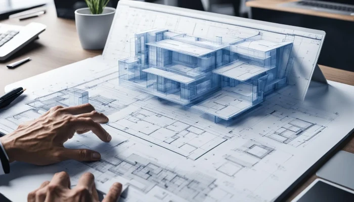
When designing modern office buildings and IT-focused environments, architects and engineers rely heavily on precision, collaboration, and foresight. One of the most critical tools they use in the early stages of design is the CAD (Computer-Aided Design) drawing—especially those provided by material manufacturers. These detailed digital files serve as the blueprint for integrating essential building materials such as raised access flooring, acoustical ceilings, HVAC systems, carpet, lighting, and more. Together, these elements shape the function, comfort, and technology readiness of the final space.
But how do these professionals actually use these CAD drawings, and why are they so important? Let’s take a closer look at how material-specific CAD drawings contribute to modern architectural and engineering workflows, with a spotlight on raised flooring systems by Pro Access Floors.
The Role of CAD Drawings in Commercial Building Projects
CAD drawings are not just technical diagrams—they’re the visual language shared among architects, engineers, interior designers, contractors, and project managers. Manufacturer-supplied CAD files include exact dimensions, specifications, and compatibility guidelines that help professionals integrate products directly into their building models. This reduces guesswork, minimizes construction errors, and saves time during both design and installation phases.
In office and IT environments, where spatial efficiency, airflow, cable management, and acoustics are paramount, these drawings become even more valuable.
Raised Access Flooring: A Foundation for Flexibility
One of the most frequently used components in IT and commercial office space is the raised access flooring system, and Pro Access Floors is a leader in this space. These modular floors provide a hidden plenum for power, data cabling, and HVAC distribution—critical needs for data centers, tech startups, and any business with evolving IT infrastructure.
Architects and engineers download Pro Access Floors’ CAD drawings to incorporate system specifications—including panel sizes, pedestal heights, and stringer configurations—directly into their building models. This allows them to:
Ensure proper floor-to-ceiling heights
Coordinate underfloor air distribution (UFAD)
Avoid conflicts with structural elements and MEP (mechanical, electrical, and plumbing) systems
Design for future adaptability in high-tech environments
To see how raised flooring supports modern office design, check out this article from Pro Access Floors:
How Architects, Engineers & Designers Use Raised Flooring in Modern Spaces
Acoustical Ceilings: Quieting the Workplace
Open-plan offices are known for collaboration—but they’re also notorious for noise. That’s where acoustical ceiling systems come in. Designers use manufacturer CAD files for ceiling tiles, suspension grids, and baffles to ensure acoustic performance while coordinating with lighting and HVAC ducts.
Engineers rely on these files to align ceiling layouts with sprinkler heads, speakers, sensors, and return air vents. By integrating acoustical ceiling details early in CAD models, teams avoid costly coordination issues during construction.
Popular ceiling manufacturers such as Armstrong, CertainTeed, and USG provide comprehensive CAD libraries, making it easy to download ceiling solutions that match both function and design intent.
HVAC Systems: Comfort, Airflow, and Efficiency
Mechanical engineers play a huge role in ensuring office spaces are not just comfortable, but energy-efficient and code-compliant. They use HVAC manufacturer CAD drawings to model everything from ductwork and diffusers to rooftop units and VAV (Variable Air Volume) boxes.
These components often take up a lot of space in ceiling cavities and mechanical rooms. With detailed CAD drawings, engineers can plan for:
Proper airflow and thermal zoning
Placement of sensors and thermostats
Coordination with lighting, ceiling grids, and raised floors
Compliance with LEED and energy efficiency guidelines
In IT-heavy environments, precision cooling—especially for server rooms—is crucial. Integration of HVAC system drawings with Pro Access Floors’ underfloor airflow layouts is a frequent and essential part of the process.
Commercial Carpet and Floor Finishes: Aesthetic Meets Function
While it may seem secondary, carpet and flooring manufacturers also provide CAD blocks and layout tools to assist designers with pattern, seam, and transition planning. Products from companies like Interface, Mohawk, and Shaw Contract come with CAD files that include pattern dimensions, backing details, and even LEED-related data.
In projects using raised access flooring, carpet tile selection is often directly influenced by the floor panel layout. Designers rely on carpet CAD tools to:
Align carpet seams with access panel joints
Reduce material waste
Create functional zones using different colors or textures
Select adhesives or installation methods compatible with modular flooring
Lighting and Electrical: Precision Placement is Key
Lighting manufacturers like Lithonia, Cooper Lighting, and Philips offer CAD files that help architects and engineers position light fixtures in coordination with ceiling layouts, window placement, and daylighting strategies.
Electrical engineers use these drawings in tandem with switchgear, power distribution units, and raceway system CAD files to:
Design efficient lighting control systems
Ensure compliance with energy codes and emergency lighting standards
Coordinate fixture locations with acoustical baffles or HVAC vents
Again, when raised flooring is in the mix, electrical engineers will also model how power will be distributed under the floor, especially in high-density IT environments.
Integration Through BIM and 3D Modeling
In today’s digital-first construction environment, most CAD drawings from manufacturers are designed to work within BIM (Building Information Modeling) platforms such as Autodesk Revit. This allows for full 3D integration and clash detection between different building systems.
For example, an architect might place Pro Access Floors’ system into a Revit model to visualize how it works with underfloor wiring and HVAC ducts. At the same time, an MEP engineer can model the overhead ductwork and sprinkler system to ensure everything fits without conflict.
The power of these manufacturer-supplied CAD drawings lies in their accuracy and compatibility across disciplines.
The Result: Streamlined Projects and Future-Proof Spaces
By incorporating CAD drawings from manufacturers across all trades and materials, architects and engineers are able to:
Reduce RFIs (Requests for Information) during construction
Speed up design approvals
Optimize energy efficiency and indoor comfort
Enhance maintainability and adaptability for future needs
Deliver higher-quality buildings within budget and on time
Whether it’s designing a tech campus, a financial headquarters, or a co-working hub, the ability to visualize and integrate complex systems early is key—and
manufacturer CAD drawings are the backbone of that process.


