
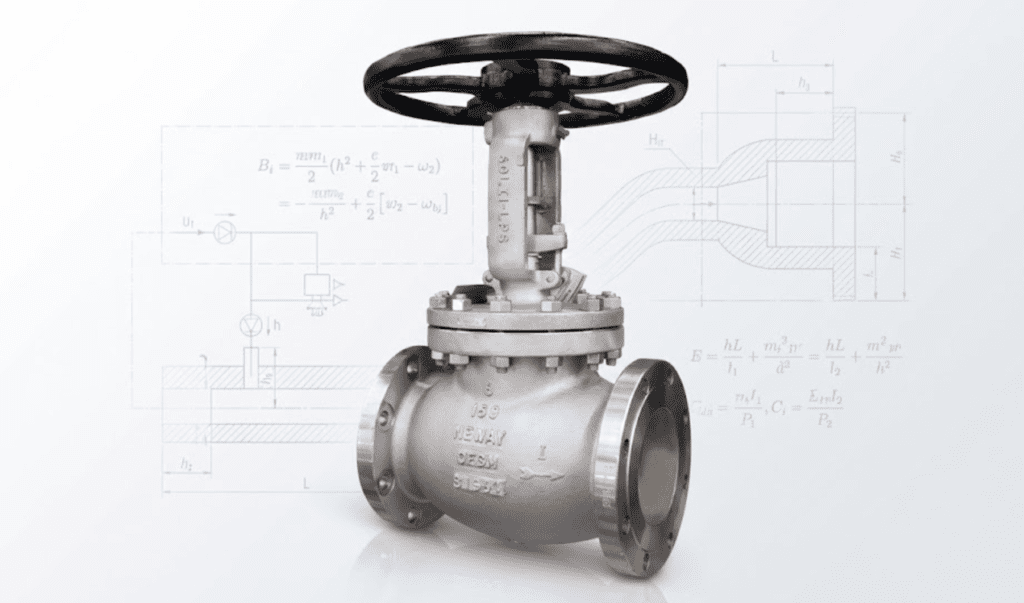
In my decades of working with fluid dynamics and process control, I have seen one mistake repeated more often than any other: treating a control valve like a simple piece of pipe. Too often, engineers simply match the valve size to the line size. While this might work for an on-off isolation valve, it is a recipe for disaster when it comes to throttling.
If you get the globe valve sizing wrong, you aren’t just risking poor performance; you are inviting physical damage through noise, cavitation, and vibration that can tear a piping system apart.
Drawing on the technical methodology used by manufacturers like Neway Valve, this guide will move beyond the basics and dive into the precise calculations required to optimize process variability and plant profitability.
Why Proper Sizing Matters: More Than Just Flow
Before we touch a calculator, we must understand the stakes. The goal of control valve sizing is not just to pass fluid; it is to modulate flow to maintain a process variable (like temperature or pressure) at a set point.
If a valve is oversized (the most common error), it forces the valve to operate at very low opening percentages—often below 10-20%—to control the normal flow. At these low openings, the friction on the seal increases, and the gap between the plug and seat becomes tiny. This leads to a loss of control resolution and can cause the valve to act like a “quick opening” device, resulting in an unstable, hunting control loop.
Conversely, an undersized valve acts as a bottleneck, creating excessive pressure drop (Delta P) that wastes energy. Worse, high velocities in an undersized valve can trigger cavitation (in liquids) or aerodynamic noise (in gases), both of which are destructive.
Key Parameters in Globe Valve Sizing
To size a valve correctly, you need to speak the language of flow mechanics. There are three pillars we must define clearly:
- Flow Coefficient (Cv)
Cv is the currency of valve sizing. By definition, a Cv of 1 represents the flow of water at 60°F (in gallons per minute, GPM) that passes through a valve with a pressure drop of exactly 1 psi. It is a measure of the valve’s flow capacity based on its internal geometry and stroke.
- Pressure Drop (Delta P) and Choked Flow
We must distinguish between “allocated pressure drop” and “actual pressure drop.” The actual Delta P is determined by the system’s hydraulics, not the valve itself. Crucially, you must check for Choked Flow. This occurs when the fluid velocity reaches a physical limit (sonic velocity for gases). At this point, lowering the downstream pressure (P2) further will not increase the flow rate. Failing to account for choked flow is a primary cause of sizing errors in gas applications.
- Fluid Properties
You cannot size a valve without accurate data on Specific Gravity (SG), Viscosity, and Temperature.
- Viscosity: If you are handling viscous fluids where the Reynolds number drops below 3500, the standard Cv calculation must be corrected.
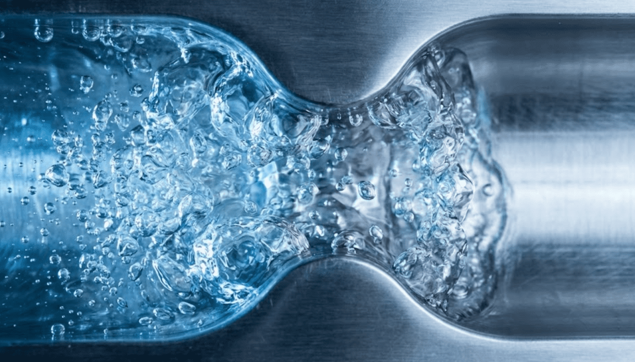
- Vapor Pressure (Pv): This is the critical indicator for phase changes. If the pressure inside the valve drops below Pv, the liquid will flash into vapor, leading to flashing or cavitation damage.
Step-by-Step Sizing Procedure (The Engineering Method)
When I consult on complex projects, I use a standardized workflow similar to the engineering logic employed by Neway Valve. Here is the 5-step procedure for accurate globe valve selection.
Step 1: Gather Process Data
Don’t guess. You need a complete data sheet containing:
- Fluid Type and State
- Inlet Pressure (P1) and Outlet Pressure (P2)
- Flow Rates: Maximum, Normal, and Minimum
- Temperature and Vapor Pressure (Pv)
- Critical Pressure (Pc)
Step 2: Estimate the Required Cv Range
We calculate the required Cv for both the maximum and minimum flow conditions. For a standard liquid (non-viscous, sub-critical flow), the governing equation is:
Cv = Q × SquareRoot(Gf / Delta P)
Where Q is flow rate in GPM, Gf is specific gravity, and Delta P is pressure drop in psi.
Calculating the Cv at minimum flow is just as important as maximum flow because it determines if the valve can turn down low enough to control the process during startup or low-load conditions.
Step 3: Select Trim and Flow Characteristics
This is where the valve internal design—the trim—comes into play.
- Equal Percentage: Best for pressure control loops or systems where the system pressure drop varies significantly with load.
- Linear: Ideal for level control or systems with constant system gain.
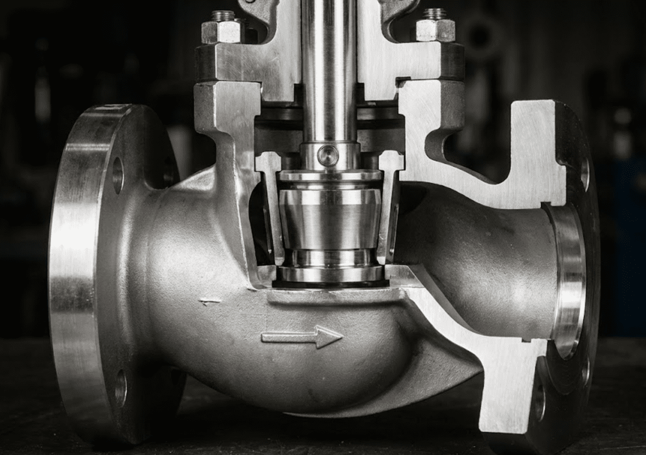
Advanced manufacturers like Neway utilize cage-guided trim designs. The beauty of a cage-guided valve is its flexibility; you can often change the flow characteristic (from Linear to Equal %) simply by swapping the cage, without changing the valve body.
Step 4: Verify Rangeability
Rangeability is the ratio of the maximum controllable flow to the minimum controllable flow. We must ensure the selected valve does not enter the “dead band”—a zone where the valve cannot mechanically resolve small signal changes—at minimum flow.
Step 5: Check for Noise and Cavitation
Finally, we calculate the Cavitation Index, often denoted as Sigma (σ).
- Flashing: Occurs if P2 < Pv (Outlet Pressure is less than Vapor Pressure). This is a system phenomenon that the valve cannot stop, but we can mitigate damage using hardened materials.
- Cavitation: Occurs if the pressure drops below Pv inside the valve but recovers above Pv at the outlet. The implosion of bubbles causes severe erosion.

Common Sizing Mistakes and How to Avoid Them
Even experienced engineers trip up on these nuances.
1. The “Safety Factor” Trap (Oversizing)
Engineers often add a 20% safety margin to the flow, and another 20% to the Cv. The result is a massive valve that operates at 5% open. This leads to “chatter,” high wear on the seat, and poor control. Trust the calculation. A valve operating at 60-80% open is a healthy valve.
2. Ignoring the Pressure Recovery Factor (FL)
Not all valves recover pressure the same way. Globe valves generally have a high FL (low pressure recovery) compared to ball or butterfly valves. This makes globe valves superior for resisting cavitation, but you must use the correct FL value when calculating if the flow is choked.
3. Misunderstanding Two-Phase Flow
If a liquid flashes into steam across the valve, you have two-phase flow. You cannot calculate this as a liquid or a gas; it requires specific thermodynamic calculations to size the outlet port correctly to handle the rapid expansion of volume.
Neway Valve’s Approach to Throttling Solutions
When standard calculations reveal difficult conditions—such as high pressure drops or cavitation risks—off-the-shelf valves often fail. This is where specialized engineering is required.
Neway Valve approaches these challenges with specific trim technologies:
- Multi-Stage Depressurization: For high-pressure drop applications (like boiler feedwater), Neway utilizes multi-stage trims. By breaking the pressure drop into several small steps rather than one large drop, the velocity is controlled, effectively preventing cavitation and reducing noise.
- Cage-Guided Stability: In high-vibration environments, Neway’s cage-guided control valves provide continuous guidance to the valve plug, reducing mechanical vibration and extending seal life.
- Severe Service Solutions: In Power Plant or Oil & Gas applications, dealing with steam requires specialized noise-attenuating trims (like labyrinth disks) which Neway engineers customize based on the specific mass flow and pressure data.
Conclusion
Correct globe valve sizing is a balance of mathematics and experience. It starts with accurate process data, moves through rigorous Cv and Delta P calculations, and ends with selecting the right hardware to handle the physical realities of the fluid.
Remember, a control valve is an investment in your plant’s efficiency. A properly sized valve provides smooth control, reduces maintenance costs, and improves safety.
If you are dealing with complex process data or severe service applications, don’t rely on simple online calculators alone.
Would you like to verify your current valve calculations? Contact Neway Engineers for specialized Valve Sizing Support to ensure your next project operates at peak efficiency.