
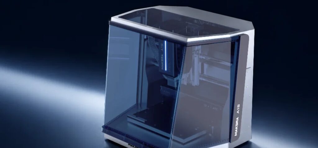
A mounting hole needs to move. An enclosure needs more clearance. A bracket fits the assembly but leaves too little space for a connector. For small hardware teams, these changes are a normal part of development. Each one becomes more disruptive when evaluating it requires another manufacturing order.
Desktop CNC machines offer a way to bring selected metal prototyping tasks closer to the people making design decisions. With suitable equipment, tooling, and machining skills, teams can produce small components, test them in an assembly, and use the results to guide the next revision.
The value lies in shortening the feedback loop between a digital design and a physical part.
The Challenge of Repeated Prototype Revisions
A CAD model can help a team check geometry, but physical assembly often reveals details that are difficult to judge on screen. Fasteners may be awkward to reach, cables may bend differently than expected, or a component may need a different mounting position.
Consider a team developing a small robotics assembly. Its first aluminum mounting plate establishes component locations. After assembly, the team discovers that a sensor needs additional clearance. A second version changes the mounting pattern and adds a pocket.
When suitable machining capability is available internally, the team can schedule that revision around its own development priorities. The process still requires CAM programming, setup, cutting, and inspection, but it gives designers more direct control over when the next test can happen.
This is especially useful when several modest revisions are likely before a design is ready for production.
Which Parts Make Sense to Machine In-House?
The strongest starting candidates are small parts with accessible features and clear test objectives. Mounting plates, brackets, enclosure panels, adapters, and simple fixtures can all be worth evaluating.
Material should follow the purpose of the prototype. Aluminum may suit a lightweight structural component, while brass or copper may be relevant to a particular mechanical, electrical, or thermal requirement. A plastic model can still be useful before committing to metal.
Part geometry matters just as much. A plate with holes and shallow pockets may be straightforward to plan, while deep cavities, thin walls, or features on several faces can require more demanding tooling and workholding.
Teams should also account for the space occupied by clamps, fixtures, and cutting tools. A part that fits within the machine’s nominal travel may still be difficult to hold or reach.
An effective first project answers a specific question: Does the mounting pattern fit? Can the connector be installed? Is there enough clearance? Defining that question helps keep the prototype manageable.
What to Look for in a Desktop CNC
Choosing a machine starts with the parts the team expects to make repeatedly. Spindle power and speed are relevant, but they need to be considered alongside frame rigidity, toolholding, axis motion, and material support.
The complete workflow deserves equal attention. A team needs to move from CAD to CAM, verify toolpaths, establish the work origin, secure the stock, and inspect the finished component. Software compatibility and practical setup procedures can affect how easily machining becomes part of everyday development.
Tool changes are another consideration. A component might use one cutter for roughing, a smaller cutter for detail work, and another tool for chamfering. Manual changes may be practical for occasional prototypes. Automatic tool changing becomes more relevant when programs regularly require several tools.
Workspace planning should include chip management, any required lubrication equipment, maintenance access, and a stable supporting bench. Staff also need time to develop machining skills and validate cutting parameters.
Where the Makera A1S Fits
The Makera A1S desktop CNC machine is one option for teams evaluating this workflow. Makera specifies a 600W spindle with closed-loop speed control up to 24,000 rpm, an enclosed frame, and ball-screw drives on all three axes.
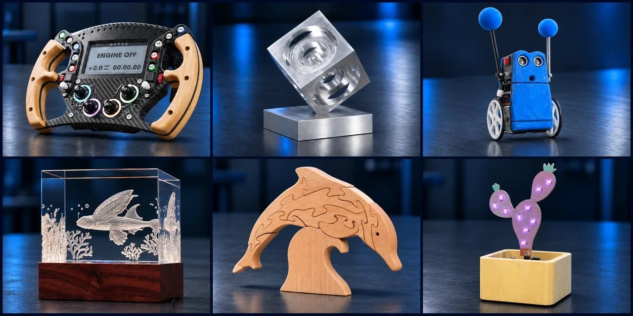
The platform is optimized for aluminum, brass, and copper. It also supports steel machining under appropriate cutting conditions, using suitable tooling and recommended parameters. This gives teams scope to explore harder materials while matching each project to the machine’s capabilities.
Two versions address different tool-changing needs. The standard A1S uses manual quick tool changes, while the A1S ATC provides 12-position automatic tool changing. Their listed work areas are 300 × 200 × 130 mm and 300 × 150 × 130 mm respectively, with the ATC tool rack accounting for the reduced Y-axis travel.
Optional minimum quantity lubrication requires the MQL accessory and an external air compressor. Teams can assess that addition alongside their intended materials and cutting operations.
These choices let buyers weigh working space, tool-changing convenience, and accessory needs against their expected prototype workload.
A Shorter Path from Design to Testing
Desktop CNC can give small hardware teams greater control over selected stages of product development. Its practical value comes from turning a design change into a part that can be assembled, measured, and tested.
For teams considering equipment such as the Makera A1S, the best starting point is a repeatable group of suitable parts and a clear plan for operating the machine. That makes internal prototyping a useful part of a broader manufacturing strategy.