
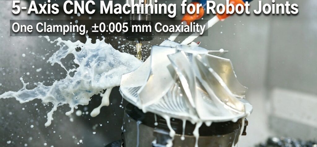
5-Axis CNC Machining for Robot Joints: Where ±0.005 mm Actually Comes From
Quick answer: Five-axis machining holds ±0.005 mm on a robot joint because every rotary feature — the two bearing bores, the spigot face and the mounting flange — is cut in one clamping from a single datum. Each re-clamp on a 3-axis mill adds 0.02–0.03 mm of re-indication error, so a housing flipped three times spends roughly 0.1 mm of its tolerance before finishing starts. Two or more features that must stay coaxial justify the process; one flat face and four holes do not.
Why Does a Robot Joint Need a Single-Setup Machining Strategy?
A robot joint holds its accuracy because every rotary feature is cut from one datum, not because the machine happens to have five axes. Machined in separate clampings, two bearing bores and a mounting flange each re-establish the part origin on relocation, and each one adds its own deviation to the chain.
Where 0.1 mm Disappears Before the First Finish Pass
Manual re-indication on a 3-axis mill runs 0.02 to 0.03 mm per flip; that figure comes from 210 joint housings that passed through our fixture review between 2024 and 2026 (Source: internal fixture review log, n=210). A housing with a bore, a counterbore and a flange face is commonly flipped three times. Roughly 0.1 mm of the drawing tolerance is gone before a cutter touches finishing stock. Five-axis contouring removes those flips, not because the axes are faster, but because the part never leaves the fixture.
Coaxiality Carries Most of the Error Budget
A six-axis wrist distributes positioning error across all of its joints, and inside one joint the two bearing seats take the largest share while face runout takes the remainder. Three thousandths of drift at the wrist shows up as path deviation at the tool centre point, and it usually gets blamed on the controller rather than the housing. So when buyers compare 5 axis cnc machining services, the useful question is not how many axes a supplier lists. It is whether they can show the fixture plan and the datum scheme that keeps both bores in one coordinate system.
Which Material and Cutting Choices Protect the ±0.005 mm Bore?
A joint is a compromise between stiffness and inertia, and the cutting strategy has to follow that compromise rather than fight it. The same 0.005 mm applies to an aluminium actuator body and to a hardened steel bearing seat, yet each is protected by different means.
7075-T6 Aluminium and the 1.5 mm Wall Problem
7075-T6 plate specified under ASTM B209 carries roughly 1.8 times the yield strength of 6061-T6 at almost the same density, which is why lightweight actuator housings default to it. The weakness is residual stress. Roughing one side of a 1.5 mm wall releases stress unevenly and bows the part before finishing. Shops that treat precision machining as a datum discipline rough symmetrically, pause for stress relief, and keep stock removal balanced between walls so the bore is still cylindrical after unclamping.
42CrMo4 at 28–32 HRC and the Flank Wear Trade-off
Where bearing seats carry reversing torque, 42CrMo4 quenched and tempered to 28–32 HRC holds seat geometry far longer than a soft alloy. Harder is not freer-cutting. Flank wear accelerates, feed rates drop, and a dull edge will push a bore out of tolerance on the last pass rather than the first. Tool change intervals belong in the process sheet next to the coating spec.
What Does a Real Cobot Joint Look Like in One Clamping?
A 120 mm outer-diameter hollow rotary flange for a collaborative robot shows how these decisions interact.
A 120 mm Hollow Rotary Flange, One Fixture Origin
The part carries a harmonic-drive flexspline spigot and a crossed-roller bearing seat, with cabling routed through the hollow body, so wall thickness at the seats stays at 1.5 mm rather than being thickened for rigidity. Both seats must hold coaxiality inside 0.005 mm, and the spigot face has to sit square to that same axis. Miss that and the strain-wave gear runs with an axial wobble that quietly shortens its service life.
What 800 Parts of Inspection Data Showed
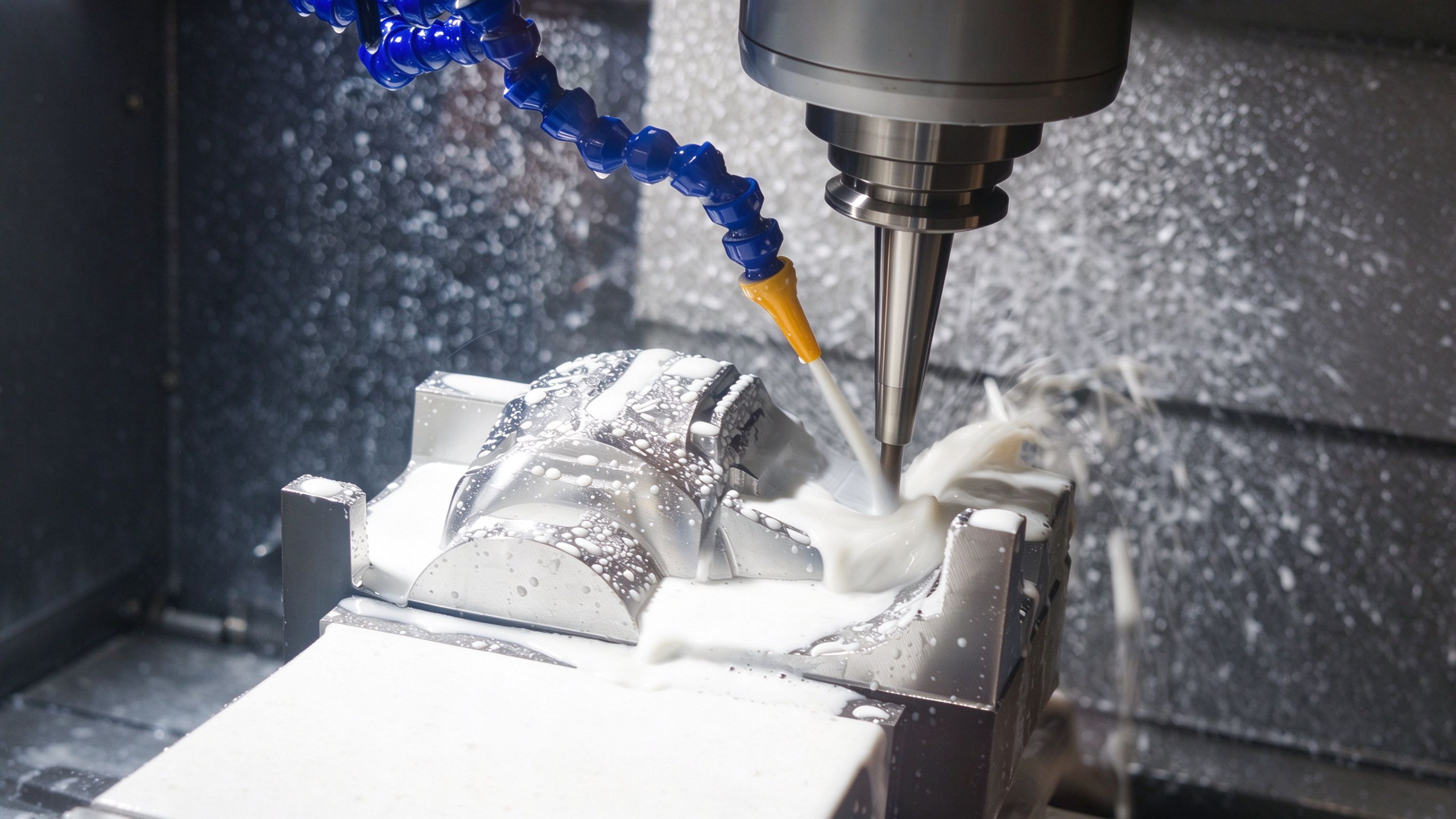
The job ran as one clamped operation on a five-axis machining centre: bore, spigot, seat and cable channel all referenced to a single fixture origin, tool tilted to reach the inner seat without a long overhang. CMM data from the LS Manufacturing robot joint programme, more than 800 parts across this geometry family, shows dimensional spread tracking fixture repeatability rather than spindle accuracy. The takeaway for a young engineer is blunt: a part that goes back into the vise twice will drift twice.
How Do You Specify the Datum Set, and When Is 3-Axis Still the Right Call?
Half of the tolerance is decided before the quote, on the drawing.
Specify the Datum Set Before You Request a Quote
- Mark the mounting flange face as the primary datum and the bearing bore axis as the secondary, on the drawing itself. Do not leave datum selection to the supplier.
- Call out coaxiality between the two bearing seats, and face runout of the spigot to that same axis, following the ASME Y14.5-2018 convention rather than a general profile tolerance over the whole housing.
- State the wall thickness you can accept, and ask whether the shop will rough, stress-relieve and finish, or cut to size in one pass.
- Request the fixture concept with the quote. A supplier who cannot describe how the part is held cannot explain why the tolerance holds at volume.
- Ask for first-article CMM data on coaxiality and runout, not a dimensional report that lists every diameter as good.
When 3-Axis Milling Wins on Price
Three-axis milling is the cheaper, faster answer for flat base covers, cosmetic shells and brackets that carry no cable routing and no bearing interface. Those parts gain nothing from a rotary table: there is no second bore to align, so single-setup cutting solves a problem the part does not have.
| Dimension | 3-axis milling | Indexed 3+2 positioning | Continuous 5-axis contouring |
|---|---|---|---|
| Spatial access | Normal-plane cutting only; no undercut or angled oil groove | Index, tilt, cut in segments; cutter angle fixed per segment | Cutter orientation follows the surface normal continuously |
| Coaxiality across datum | Manual flip and re-indication; ±0.1 mm class stack-up | Fewer flips; ±0.03 mm class indexing error | All rotary features from one clamp; ±0.005 mm class |
| Cutter overhang and chatter | Long tools, L/D above 5:1; deflection common | Medium overhang; transition marks at segment joints | Short rigid tools; Ra 0.8 µm achievable in flank milling |
| Typical joint parts | Flat base covers, brackets without cable routing | Orthogonal bores in cubic reducers, junction boxes | One-piece hollow flanges, routed torque-sensor bases |
The threshold is functional, not philosophical. Three rules cover most of the drawings we see:
| If the drawing has… | Quote it on… |
|---|---|
| Two or more features that must stay coaxial, or a bore meeting a face at an angle the vise cannot present | 5-axis, one clamping |
| Orthogonal bores in a cubic reducer or a junction box, no compound angle | 3+2 indexing is enough |
| One flat face and four holes, no bearing seat | 3-axis, and expect a lower price and a shorter lead time |
Telling a customer that a 3-axis shop will beat us on a bracket is part of doing the job properly. The fixture concepts, datum schemes and CMM acceptance criteria behind those calls sit on our Precision Machining service page.
Conclusion
Joint accuracy is decided at the drawing and the fixture, not at the spindle. Specify the datum set, keep critical features in one clamping, and let the material dictate how the stock comes off. LS Manufacturing quotes robot joint housings this way, and we will say so when a simpler process is the better answer for your part.
FAQs
Why do robot joints need 5-axis machining instead of a 3-axis mill?
Because the two bearing seats and the mounting flange must stay in one coordinate system. Multi-setup cutting re-datums the part on every flip and adds 0.02–0.03 mm per relocation, which consumes the joint's error budget before finishing begins.
Does 5-axis machining remove the need for surface treatment?
No. Anodising under MIL-A-8625 adds corrosion resistance and does not correct geometry. Machining sets the Ra and the dimensional accuracy; coating thickness and masking are separate decisions that belong on the drawing.
What is the minimum wall thickness for a 7075-T6 actuator housing?
Around 1.5 mm for cantilevered sections near bearing seats. That limit is set by chatter and residual stress rather than by the cutter: thinner walls deflect under cutting force and bow after unclamping, so stiffness has to come from geometry.
How is coaxiality checked before a joint ships?
A coordinate measuring machine measures both bores against the declared datum axis, and the report shows the coaxiality value plus spigot face runout. Individual bore diameters alone do not prove the joint will assemble without preload or wobble.
Can a 3-axis shop hold ±0.005 mm on a joint housing?
Occasionally on a single-face part, rarely on a hollow housing with crossed bores. Re-clamping costs more tolerance than most 3-axis machines lose to their own accuracy, so the process route matters more than the machine specification sheet.
Author Bio
With 15+ years of experience, Gloria specializes in precision CNC machining, 3D printing, urethane casting, rapid tooling, injection molding, metal casting, sheet metal, and extrusion. Dedicated to helping engineering teams optimize DFM and scale seamlessly.